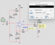
is C7 the secret to preventing any op amp driven amplifier from oscilating that ive been looking for?This is the most simple way I found to make a good 3W amplifier for 4 Ohm.
Supply is 16V and this is what comes from a 12VAC transformer.
Actually it gives a little more than 3W.
Distortion is rather low.
C7 has NOTHING to do with stability. It’s an AC bypass for the bias stack.
You probably want to put a lead compensation cap across the feedback resistor if the closed loop gain is set lower than about 10.
Voltage gain of the buffers is unity. Oscillation won’t be a severe problem unless supply decoupling is poor. Then anything goes.
You probably want to put a lead compensation cap across the feedback resistor if the closed loop gain is set lower than about 10.
Voltage gain of the buffers is unity. Oscillation won’t be a severe problem unless supply decoupling is poor. Then anything goes.
If you like how it sounds in its original form, you should not be modernizing it.Hello,
I will be modernizing old Yugoslavian radio called Iskra Savica SN120.
In the process I will remove all electronics and I need a suitable amplifier.
It has oval (10x15cm paper membrane) full range speaker -full range with high sensitivity.
Enclosure is not completly sealed, it has backplate with many holes, like radios did have back in the day.
Those radios (when working correctly) have really nice warm sound that somehow fills the whole house, it also has strong mids.
This is the sound that I would like to keep.
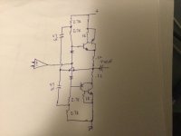
Here is the schematic of original amplifier and I'm thinking of building the same one, except for better power supply:
View attachment 1355362
What do you think of it? Is this class A?
Do you see any room for improvements?
Edit: I had just realised that AC187K and AC188K output transistors are germanium... can I substitite them for something newer? Also should I substitute other transistors with something newer?
I know that this amp goes nice with the speaker, would you recommend different amp anyway?
View attachment 1355363
This is not the exact speaker, but it's similar enough.
View attachment 1355364
Thank you
You should not replace original germanium amplifier, just replace old electrolytic capacitors.
You will not be able to match that sound with modern chip amplifiers or small classA amplifiers.
Its should be pretty easy to make it sound better though.

it seems that ltspice has weird models thenC7 has NOTHING to do with stability. It’s an AC bypass for the bias stack.
You probably want to put a lead compensation cap across the feedback resistor if the closed loop gain is set lower than about 10.
Voltage gain of the buffers is unity. Oscillation won’t be a severe problem unless supply decoupling is poor. Then anything goes.
If you like how it sounds in its original form, you should not be modernizing it.
You should not replace original germanium amplifier, just replace old electrolytic capacitors.
You will not be able to match that sound with modern chip amplifiers or small classA amplifiers.
Its should be pretty easy to make it sound better though.
One would have to replace (or update) if the Ge devices were dead. I’ll bet I could match the sound using a modern chip amplifier. But the circuit required would be far more complicated than it needs to be, and run off a lot more voltage. It would also take more than one chip. Copying the data sheet application circuits is not how to do it.
I believe the sound of the radios was due to the cabinet size and shape as well, it looks like a design that was earlier used for the old valve radios.
The volume is much larger than on new speakers, and the driver design also has an influence.
First, I would check the driver for response, and the radio section, if working.
And I would try a 12V chip amp like the 6283 (50 cents assembled PCB here in India), it is very common in small FM radios.
Earlier, it was a plastic film variable cap tuner, with a 1619 tuner / amp chip (same price), that is good for a small radio.
Now they use a FM radio kit, digital tuner, driving a single channel of the stereo 6283. The chip is good from 9-16 volts, so some leeway is available.
The FM kits have sound equalizer presets, that is a facility which may be useful. they also allow line in, so the existing radio section can be routed through that if needed.
The 810 chip is obsolete here in India.
OK....Input impedance is 50k (two 100k parallel equivalent). The cap is a short to audio.
You will need 18-20 V to get 3W - you need the full 16V at load. D44/D45H will work. You need trannies with high(er) gain than TIPs or BD’s.
IF you use low speed low gain junko transistors (ie, all you can get) run them in CFP with a pair of 2N3904/6, MPSA06/56, BC237/337, etc. and you will get substantially the same result.
5532 op amp can be used too. LF351 does not have enough output current, unless the CFP follower approach is used. If you do that the 1k to ground can go to 4.7 or 10k, to reduce heating in the op amp.
Thank you for clarification.
I'm reading about CFP right now. If needed I will draw a schematic and post it here to make sure it's good.
Do I need to use CFP approach with D44 / D45H also?
If I use 5532, do I need to modify anything else?
1k to gnd changes to 4.7k-10k if 5532 is used, LF351 is used or if CFP approach is used? Sorry I cant wrap myself around this part.
It is a design that was earlier used for valve radios. I think that this is the first transistorised radio that "Iskra" produced. At that time they had made many valve radios.I believe the sound of the radios was due to the cabinet size and shape as well, it looks like a design that was earlier used for the old valve radios.
The volume is much larger than on new speakers, and the driver design also has an influence.
First, I would check the driver for response, and the radio section, if working.
And I would try a 12V chip amp like the 6283 (50 cents assembled PCB here in India), it is very common in small FM radios.
Earlier, it was a plastic film variable cap tuner, with a 1619 tuner / amp chip (same price), that is good for a small radio.
Now they use a FM radio kit, digital tuner, driving a single channel of the stereo 6283. The chip is good from 9-16 volts, so some leeway is available.
The FM kits have sound equalizer presets, that is a facility which may be useful. they also allow line in, so the existing radio section can be routed through that if needed.
The 810 chip is obsolete here in India.
I had tryed connecing the speaker in it's cabinet to the Yamaha amplifier and it lacks mid tones compared to original.
I'm not to happy about using such kits, quality IMHO is ussualy mediocre at best. I have working tuner from Sony car radio, finding that was a result of climbing over a pile of diy FM modules.
Most simple is to replace the inverting amp part with a TDA2030 with gain set at 68 and connected as inverter,
this way the original tone control can be kept as it is while the TDA2030 will provide HiFi class perfs, this chip
is still available at 3€ or so for a STM.
Also what is possible in this case is to use the transfo s 2 x 12V5 capability to feed the TDA with +-15V while keeping
the rest at single rail +15V5, this require only a 3A diodes bridge and a 2200uF cap, power would rise to 12-15W/4R,
of course with another speaker but a car dedicated one is cheap.
At 15.5V a TDA2030 will do 3W/4R, so that s not an issue, the advantage is the simplicity with a single TO220
package, 4 resistances and no cap needed since they are already on the circuit, and of course a cost of less than 5€
for a sound that will be as good.
Anyway if you go the discrete route, and why not, good luck with the mod.
package, 4 resistances and no cap needed since they are already on the circuit, and of course a cost of less than 5€
for a sound that will be as good.
Anyway if you go the discrete route, and why not, good luck with the mod.
This is what I'm intending to do. I just must wait till monday for store to open to gather the parts.
I'm still affraid that I will get the "tinny" sound if I use such low power ic. I really need alot of mids.At 15.5V a TDA2030 will do 3W/4R, so that s not an issue, the advantage is the simplicity with a single TO220
package, 4 resistances and no cap needed since they are already on the circuit, and of course a cost of less than 5€
for a sound that will be as good.
Anyway if you go the discrete route, and why not, good luck with the mod.
I was always building amplifiers with ICs, but would like to go the other way on this project and I need split rail for the preamp.
OK....
Thank you for clarification.
I'm reading about CFP right now. If needed I will draw a schematic and post it here to make sure it's good.
Do I need to use CFP approach with D44 / D45H also?
If I use 5532, do I need to modify anything else?
1k to gnd changes to 4.7k-10k if 5532 is used, LF351 is used or if CFP approach is used? Sorry I cant wrap myself around this part.
CFP followers have increased current gain, and are easier to drive. You lose about 3 Vbe from the available voltage instead of only two. Regardless of what op amp is used I’d use them. You don’t need the high speed high gain outputs. BD441, TIP41, and the like can be used. The small signal drivers should be “beefy” ones, although I’ve used 2N3904/6 with up to +/-18 (ie 36 volt) supply and the output stage doesn’t go into thermal runaway. If I were using an op amp I’d end up with something like this, boot strapping both sides of the driver. Op amps themselves already lose about 3 volts to each rail, and the boot strap allows you to make this up.
But you see all this and you go “Time out, it’s already getting complicated”. I could accomplish with two miserable transistors and the same number of other components, what the op amp does. And you get to ditch the boot strap on one side. Overall, a simpler circuit. More like the original. This is why I’d probably just go back to the original circuit, adding the two bias diodes and using silicon outputs. It already has a pretty damn well optimized driver stage, although if lower gain (ie BD or TIP) outputs are used I’d consider increasing the tail current in the driver.
But no one has addressed the elephant in the room yet - which is the frequency response shaping network in the feedback of the power amp stage. If you don’t have that, it’s going to sound tinny and small. Personally, I’d get it OUT of the power stage, but it will have to be implemented SOMEWHERE.
Attachments
I'm still affraid that I will get the "tinny" sound if I use such low power ic. I really need alot of mids.
I was always building amplifiers with ICs, but would like to go the other way on this project and I need split rail for the preamp.
It’s not the IC’s fault. It’s because overall design details of the original are being ignored. A TDA2003 operated at 16 volts is comparable to the original power. At 18 you get a wee bit more and I’d take it.
A lot of those old ICs were at fault, though, because many couldn’t even muster three watts at 26 volt supplies. And had 10% distortion trying. And if you do pre-equalize (as required to obtain your original sound) a half watt amplifier is simply going to run out of juice.

- Home
- Amplifiers
- Solid State
- Amplifier suggestion for old 3w speaker