+1. You do not want to waste a 5V drop in the CCS if you end up using this amp in a grounded bridge.
That's the goal on this project.
I would simply use the 2-transistor CCS which works down to 2Vbe.
Can you show how you would do this please?
Remember, the rails will be moving, and the diff pairs need to common-mode all the way to the rail or as close to it as possible.
Good point.
The rails move in regards to the ground that is. Basically the ground floats between the rails...
For this reason, the traditional diff pair input is not preferred. Not saying it won't work, but you will pay a couple volts penalty in output swing that you don't absolutely have to. You would get better results if the input stage runs off its own stabilized supply that is referenced to the artificial ground produced by the low side amp. The QSC circuit does this for its op amps.
Please go ahead with a schematic suggestion. We're all ears!!
What I'm also wondering is how we need to make the low side of it. For one thing it won't need a zobel nor will it need the R//L thingy.
Isn't this double diff input stage a good choice for this purpose? Its symetry is a plus I think.
And still no suggestions about how to connect those drivers to the the outputs properly, and keep the maximum of symetry?
Emitter resistors on the diff amp is a matter of figuring out how much gm you need for loop stability. In general, you will want to degenerate it - fine tuning how much can be done later.
One base-to-emitter resistor for all the 3055's in any bank. Individual base stoppers may be a good idea if you run into local stability problems. You might.
Do not use BD139/140 for drivers. Use TIP41C. You will want the current capacity. The problem with 3055's is the beta falls to about 5 at 10A. 3 of them driving 30A peaks requires 6A of base current. Even that's a stretch for a TIP41. Forget it with a BD139.
Please go ahead with a schematic suggestion. We're all ears!!
When I've got time to draw up a concept, I'll post it.
What I'm also wondering is how we need to make the low side of it. For one thing it won't need a zobel nor will it need the R//L thingy.
The low side's zobel needs to return to the rail(s).
Isn't this double diff input stage a good choice for this purpose? Its symetry is a plus I think.
Better than the single diff pair, due to good PSRR on both sides, which is required here. But op-amp input stages are better because they are totally isolated from what's going on with the rails.
And still no suggestions about how to connect those drivers to the the outputs properly, and keep the maximum of symetry?
That's a detail we don't have to consider yet. The most trouble-free version is not the one with the "best symmetry", so we'll have to consider that trade off eventually.
Emitter resistors on the diff amp is a matter of figuring out how much gm you need for loop stability. In general, you will want to degenerate it - fine tuning how much can be done later.
That's what I was thinking, and the value I chose is just a start. Maybe this value may be somewhat close to what's needed though.
My idea is to lean towards a low tim design, with less gain on each stage, more stable open loop with moderate overall gain and then a modest feedback.
One base-to-emitter resistor for all the 3055's in any bank. Individual base stoppers may be a good idea if you run into local stability problems. You might.
Are you referring to that R20 that isn't connected yet?
I thought the base resistors could be a good thing, and they don't need a high ohmic value.
Hopefully we don't need to add compensation caps on the 3055s...
What about my idea to place a decoupling cap on each 3055's collector?
I was just digging for a suitable heatsink and it's going to be a tricky choice for a workable layout. Perhaps a separate pcb for power and signal...
Do not use BD139/140 for drivers. Use TIP41C. You will want the current capacity. The problem with 3055's is the beta falls to about 5 at 10A. 3 of them driving 30A peaks requires 6A of base current. Even that's a stretch for a TIP41. Forget it with a BD139.
That is exactly why I mentioned this, because those 139/140 are rather week and the 3055's low gain at high currents was my main concern. Having tripled the 3055s compared to the original design and planning on being able to withstand a 2ohm load make me think that those BDs would be overwhelmed.
It's right. With 2.2u, it means -2db at 20Hz. With 10u, it's only about -0.4db at 20hz. Seems better.Elektor's initial value was 3 caps of 820n each, so using 2.2uF did make the value a little lower, but not that much. I tried calculating the frequency using R*C=1/(2 Pi fc) and found a -3db around 15Hz. Am I using the right formula? Using R4 for R and C3 for C.
If we go to 10uF, I calculate this at a bit less than 3.5Hz, if I'm calculating it right. Would that work better?
If you keep the 6.8k resistor, yes, the current will go up a tiny little bit. But it's not significant. The current 1w resistors are grossly oversized anyway (they dissipate about 60mW...). 1/4w resistors would probably survive forever in that position.That's a little superfluous, but if space becomes an issue during layout, that could be considered. Although it may remove a zener and cap, it still requires a resistor to set the current and that current would be a little higher than with the zeners I think, which may even require a bigger resistor than the current 1W.
As for the rest, I agree with wg_ski.
For the two-transistors ccs, just see for example the ccs under the input ltp here: SymAsym5 - Project
When I've got time to draw up a concept, I'll post it.
Great!
The low side's zobel needs to return to the rail(s).
Ah! That's good info!
Do we need 2 of them? Going from ground to the rails?
Better than the single diff pair, due to good PSRR on both sides, which is required here. But op-amp input stages are better because they are totally isolated from what's going on with the rails.
I'd be curious to see an example. But I had experience with opamps based amps before and I never could get one stable enough to work.
We're using 3055s here, but I wouldn't think of using 741s if using opamps.
It's right. With 2.2u, it means -2db at 20Hz. With 10u, it's only about -0.4db at 20hz. Seems better.
Alright then, I'll change to 10u on that one. Non polarized.
If you keep the 6.8k resistor, yes, the current will go up a tiny little bit. But it's not significant. The current 1w resistors are grossly oversized anyway (they dissipate about 60mW...). 1/4w resistors would probably survive forever in that position.
That's not what I figured. Assuming the highest "allowed" rails at 35V (too much for plain 3055s), we have 70V total, minus the 11.2 from the 2 zeners, we have 58.8V left on that 6k8, which means it would want to dissipate a little over 500mW. That's why it's a 1W. What have I missed?
Sorry, I had in mind the two 1k5/1w resistors. The 6k8 would dissipate about 300mw with 35v rails and leds. About 250mw with zeners.That's not what I figured. Assuming the highest "allowed" rails at 35V (too much for plain 3055s), we have 70V total, minus the 11.2 from the 2 zeners, we have 58.8V left on that 6k8, which means it would want to dissipate a little over 500mW. That's why it's a 1W. What have I missed?
But it's a detail... fixing the current drive of the output stage is a priority ;-)
Sorry, I had in mind the two 1k5/1w resistors.
Ah, ok, but now for sure they don't need to be 1W.
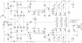
I made the changes, sch attached.
The 6k8 would dissipate about 300mw with 35v rails and leds. About 250mw with zeners.
How do you arrive at that figure with the zeners?
That resistor is between both zeners, seeing both rails minus both zeners at 5.6V, so there should be 58.8V across it. That's a bit over 500mW to dissipate. How do you calculate this to arrive at 300mW?
But it's a detail... fixing the current drive of the output stage is a priority
That's done, partially, see updated sch. The part numbering is getting messier and messier, but I'll fix this later. R8 now is moved to an other place and new resistors appear. Now remains the value of R8 and R39 to calculate. I didn't know what to do there, since they're tied to a moving ground target. Plus I guess the 1k5 R11 & R12 now may also need to be recalculated.
Attachments
No current mirrors to keep those long tail pairs in balance? From my experience, it makes a big difference.
An externally hosted image should be here but it was not working when we last tested it.
Last edited:
No current mirrors to keep those long tail pairs in balance? From my experience, it makes a big difference.
An externally hosted image should be here but it was not working when we last tested it.
I thought about that again today. I thought perhaps it's an overkill and we're adding quite a few parts and they are semi. But then again, they're only small signal TO92, cheap, barely more expensive than the resistors, and by using those, we also dispense using some of the resistors, so it's a trade off and there is no real cost issue. Even on pcb real estate it's not really a difference.
So I guess this is quite possible. Is it overkill for this purpose? Maybe, maybe not, as we're trying to squeeze as much as we can out of outdated old 3055s, whether it be power or quality. Since they're not really high end, maybe it's worth doing this to get the most out of them...
That would add 4 transistors, to replace 4 resistors. Do we do it?
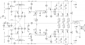
Here, I changed the sch for the current mirrors.
Substituting 4 resistors for 4 TO92s won't change much cost and pcb real estate, but if it helps giving the best shot at those 3055s, why not?
The R11 & R12 resistors still need recalculation I think.
One thing that can also be feasible, is to physically locate those current mirrors and diff amp pairs close together and in the proper direction to thermally couple them. That and a prior matching would also be nice.
And I forgot to mention, where is the most appropriate point to take the output from that mirror? I took it from the same side the input signal comes in. This is what I always saw done. Was I wrong?
Attachments
Last edited:
I'm thinking we still need resistors in the emitters on those current mirrors. Can anyone confirm this? What do we calculate them for? (if we need them)
Gentlemen,
This configuration with current mirrors will have stability problems
because of increased gain and most important of all, the VAS current
will be ill-defined. Same flaw has been extensively discussed about
one of Mr. Slone's amplifiers. The cure would be to connect the
emitter of the VAS to the emitter of the 'mirror' in the current mirror,
the current equalizing resistors will have to have different values though,
to accommodate for the voltage drop due to VAS current.
Instead of trying to get stellar performance figures for this amp, I believe
it is best to leave things as they are, because, as it is, the subjective
performance doesn't leave much to be desired anyway. I believe this amp
is a very fine example of the benefits of output triples. Rock solid stability
temperature wise and bias current wise. Hum and hiss are virtually
non-existent and the sound does not cause any fatigue at all, one can listen
to it hours on end.
Best regards
Selim
You forget the drop across the two 1500r resistors, about 3000*0.006= 18v. So there's only 70-11.2-18= 40.8v over the 6k8 resistor, not 58.8v.How do you arrive at that figure with the zeners?
That resistor is between both zeners, seeing both rails minus both zeners at 5.6V, so there should be 58.8V across it. That's a bit over 500mW to dissipate. How do you calculate this to arrive at 300mW?
r8-r39 can stay a single resistor. Make it 8k2 or so from 6k8. No need to change r11-r12, the current through them doesn't change.Now remains the value of R8 and R39 to calculate. I didn't know what to do there, since they're tied to a moving ground target. Plus I guess the 1k5 R11 & R12 now may also need to be recalculated.
Wrt the input stage, I agree with Selim.
This configuration with current mirrors will have stability problems because of increased gain and most important of all, the VAS current will be ill-defined. Same flaw has been extensively discussed about one of Mr. Slone's amplifiers. The cure would be to connect the
emitter of the VAS to the emitter of the 'mirror' in the current mirror,
the current equalizing resistors will have to have different values though,
to accommodate for the voltage drop due to VAS current.
Instead of trying to get stellar performance figures for this amp, I believe
it is best to leave things as they are, because, as it is, the subjective
performance doesn't leave much to be desired anyway. I believe this amp
is a very fine example of the benefits of output triples. Rock solid stability
temperature wise and bias current wise. Hum and hiss are virtually
non-existent and the sound does not cause any fatigue at all, one can listen
to it hours on end.
Thanks for your input.
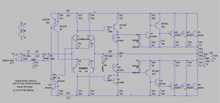
So then let's go back to plain resistors.
Attached is the updated sch, and I also found out I had swapped wrongly the driver transistors when I changed from the BD to the TIP types. This should be correct now. But remains the proper configuration on the pre-driver and driver stages, so they are properly linking up to the 3055s. I made more connections, but probably not the best ones. See sch...
Attachments

You forget the drop across the two 1500r resistors, about 3000*0.006= 18v. So there's only 70-11.2-18= 40.8v over the 6k8 resistor, not 58.8v.
Right! That's what I was missing. Ignoring wrongly those resistors, so then that 6k8 doesn't need to be 1W, an ordinary 500 or 600mW will do there.
r8-r39 can stay a single resistor. Make it 8k2 or so from 6k8. No need to change r11-r12, the current through them doesn't change.
Cool, so no need to mess with that.
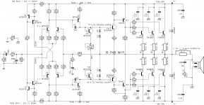
Wrt the input stage, I agree with Selim.
Ok then, new sch attached.
Attachments
Spookydd,
I believe you are on the right track now. My reservation would be not to use
TIP41C and TIP42C. Although they are much more robust than their BD
counterparts, they are that much slower as well. I believe MJE243 and MJE253
to be better choices for this purpose. For the sake of keeping things simpler,
one can opt for a single MJ15003 instead of a crowd of 2n3055's. But, DIY
audio is all about having fun, so, whatever pleases you most, just go ahead.
Cheers
Selim
- Home
- Amplifiers
- Solid State
- Amplifier based on 2N3055