Actually looking at P.7 it looks like a single supply like I specified earlier (but 80V this time) but with one side the output is grounded and power supply fully floating
- I get it now!! 🙂 Go for it lads and lassies!!
- I get it now!! 🙂 Go for it lads and lassies!!
Actually looking at P.7 it looks like a single supply like I specified earlier (but 80V this time) but with one side the output is grounded and power supply fully floating
- I get it now!! 🙂 Go for it lads and lassies!!
It's a bit unconventional, not so well known but well implemented by crown. And it does take a few readings to fully grasp the idea behind it.
I think it might be pushing it a bit to go for 80V for the 3055, but we can do 60V and a little more maybe without blinking.
The transformer can be a bit cheaper, having a single secondary winding, with no central tap. The bad thing, sort of, is that the filtering caps must withstand twice the voltage they would if in a fully symetric setup.
The 2 amps, PSU and all can be put on a single board, so all the wiring would be minimal, avoiding the mistakes around the grounding issues.
Plus, if we drive that thing from a balanced line, there is no need for the unity inverter between the amps' inputs.
". The bad thing, sort of, is that the filtering caps must withstand twice the voltage they would if in a fully symetric setup. "
Well in the P7 example they'd have to be rated for the 80V +10% for unreg supply.
Well in the P7 example they'd have to be rated for the 80V +10% for unreg supply.
". The bad thing, sort of, is that the filtering caps must withstand twice the voltage they would if in a fully symetric setup. "
Well in the P7 example they'd have to be rated for the 80V +10% for unreg supply.
That's what their example shows, but if we're using 3055s, then we should go a little lower to stay in the safe area. With various losses, the unloaded supply might be able to come somewhat close to the 80V, but would sag with the load and with the losses in the emitter resistors and a few other places, we might not overshoot on the Vce0 of those 3055s.
Maybe a compromise, 70V or so, unloaded.
Plus we can make one unique single supply for both sides, for simplicity.
Then we should be able to find suitable filter caps to handle this voltage.
With voltage increasing, the large caps get harder to find, but in this case, we don't need super large caps and we can parallel a few.
One transformer, single secondary, one rectifier bridge, maybe a few decoupling caps here and there and the filter caps, and there we have a PSU.
No need for power-on delays, we would not use a huge transformer that would require it.
I am thinking, a single board, with everything on it, with 2 wires coming from the transformer, 2 wires coming out for the speaker and we could even get away with no wires if we placed the input plugs right on the board.
This can make for a simple build, even though the design is a bit more complex than usual.

2N3055/MJ2955
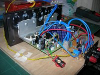
I have been listening to this amp by Selim Ardali for the past one week. Had it running almost 24 hrs. with no issues. Supply voltage at +/-26Vdc.
Pleasantly surprised with its sound quality. Very nice vocals and livelike. Bass performance is rich and thick. My setup consists JMlaB bookshelfs, diy preamp and source Audiomeca Transport/DAC.
Very very interesting amp.
Raj.
Attachments
I took an old Maplin 225WRMS 2N3055/MJ2955 based design and replaced all the transistor with better modern ones.
It sounds very good.
I also upgraded the power level to 250WRMS.
It sounds very good.
I also upgraded the power level to 250WRMS.
Plus, if we drive that thing from a balanced line, there is no need for the unity inverter between the amps' inputs.
The two amplifiers in the grounded bridge are NOT the same. The high side amp is a conventional one and a multitude of topologies will work, so long as the output of the input stage is not referenced to either rail. The low side amp is a "flying rail" amplifier like the QSC, and doesn't even require a VAS. The feedback arrangement required to make it all work is not shown in the white paper, but easy to dope out from the MA2400 schematic set.
This isn't something you're going to get working the first time, but should be very stable once the bugs are worked out.
The two amplifiers in the grounded bridge are NOT the same. The high side amp is a conventional one and a multitude of topologies will work, so long as the output of the input stage is not referenced to either rail.
Can you elaborate on that point please?
The low side amp is a "flying rail" amplifier like the QSC, and doesn't even
What's a flying rail then?
require a VAS. The feedback arrangement required to make it all work is not shown in the white paper, but easy to dope out from the MA2400 schematic set.
I have the schematics for most of those amps, and they're rather complex. Too much for any diy project for sure. But perhaps they can help understanding the big idea behind the concept.
This isn't something you're going to get working the first time, but should be very stable once the bugs are worked out.
This is making the project even more interesting. We're in for some good discussions on that one.
I was thinking we could get quite a punch for such old trannies that many have already discounted as unsuitable for audio. Those 3055s used to be main stream audio way back when, and pretty much killed the tube amps' future.
In a bridge config, with enough pairs on the outputs to drive 2 ohm loads, the bridge itself can drive a 4ohms load and we should get a nice amount of watts out of that. Of course it's nowhere near the quality standards expected nowadays, but that's not the point.
I doubt this type of setup has ever been attempted, so I think we should try it. Make it fun!!! And a learning experience in the process!

I don't think anyone mentioned Elvee's circlophone yet ?
I thought it was a little bit weird. I didn't quite understand how it works...
Gentlemen,
I really would recommend you to give the amplifier mentioned by RSK on post
#66. It is actually the Elektor amp from 1983 Summer Circuits. I modified it a
little to use complimentary pairs. It is basically a dual differential input driving
symmetrical VAS driving triple outputs. You will be surprised at how good
those ancient parts can sound when their shortcomings are properly handled.
I don't remember the exact threads now but the circuit and the article has
been posted on this forum quite few times.
Selim
Selim, your amp is cool
The thread is here http://www.diyaudio.com/forums/solid-state/242341-audio-amplifier-2n3005-3.html
This amp deserves an audition. Complete amp costs very low but the performance is unbelievable. I am sure anyone who builds it will never now whats coming until they listen to it. Please look at Elektor amp - YouTube
Complete the video to see what I mean.
Many thanks to Selim
Gentlemen,
I really would recommend you to give the amplifier mentioned by RSK on post
#66. It is actually the Elektor amp from 1983 Summer Circuits. I modified it a
little to use complimentary pairs. It is basically a dual differential input driving
symmetrical VAS driving triple outputs. You will be surprised at how good
those ancient parts can sound when their shortcomings are properly handled.
I don't remember the exact threads now but the circuit and the article has
been posted on this forum quite few times.
Selim
The thread is here http://www.diyaudio.com/forums/solid-state/242341-audio-amplifier-2n3005-3.html
This amp deserves an audition. Complete amp costs very low but the performance is unbelievable. I am sure anyone who builds it will never now whats coming until they listen to it. Please look at Elektor amp - YouTube
Complete the video to see what I mean.
Many thanks to Selim
Elektor's 2N3055 amp
Actually I was leaning towards using that one and slightly alter it for the purpose.
I would stick with the quasi config and 2N3055 but it requires more pairs.
It doesn't have protection built-in, but perhaps with 3 pairs it would withstand a short on its output, with sufficient heatsink. Can anyone propose calculations on this to make sure this would be the case?
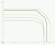
I plotted SOA graphs, with 35V rails in mind, for 2 and 3 pairs and loads of 8, 4 and 2ohms. Just for kicks, I put the SOA for the MJ15003 and 2N3773 for comparison, but I guess anyone could go that route if they wanted to use other trannies besides the venerable 2N3055.
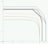
The first graph is for 2 pairs and the second for 3. Only 35V rails and resistive loads of 2, 4 and 8ohms (orange, red and green respectively). The 2N3055 SOA is the thick dark blue one, MJ15003 is the red and the other 2N3773.
If someone wanted to switch to the 2N3773 to increase rails, that looks quite feasible.
To me it looks like we have tons of headroom, although I didn't plot reactive loads. I'd love some help in using the proper equations for plotting the reactive loads...
I tried the single pairs and although it's adequate for 8ohms, the 4 ohms would be a little too close for comfort, and since the plan is to bridge, if the load on the bridge is 4 ohms, then the amps see 2ohms and we should aim for this.
Doing it this way, we can get quite a good amount of watts out of those 3055s. Using a 24V transfo might be pushing it, as the unloaded voltage might be around 27-28V, which would push the unloaded rails to above 38V, but then they'll sag and might come down to a somewhat safer area at full load. It might be better to find a transfo giving about 22V instead of 24V, keeping it a little safer.
Depending on that choice and how the rails sag under load, we should get something like a 20Vrms output, so that's a common 50Wrms on 8ohms, but that's where the bridging gets interesting, an 8ohms load on the bridge would see about 200W, not bad for 2N3055s, and if we load that bridge with 4ohms, the amps would see 2ohms and the rails would sag more seriously, but still, the power would be well above 300W, on the way to 400...
Very interesting... So if we start from a decent design and alter it to work in this configuration, we're getting quite a punch!
Please comment on all this and I'm sure I'm not the only one wanting to understand how to calculate those things. In case of a full short on the output and if we have 3 pairs of 3055s, would that sustain the abuse? Would we still be in the SOA? Then there may be no need for protection circuitry.
Actually I was leaning towards using that one and slightly alter it for the purpose.
I would stick with the quasi config and 2N3055 but it requires more pairs.
It doesn't have protection built-in, but perhaps with 3 pairs it would withstand a short on its output, with sufficient heatsink. Can anyone propose calculations on this to make sure this would be the case?
I plotted SOA graphs, with 35V rails in mind, for 2 and 3 pairs and loads of 8, 4 and 2ohms. Just for kicks, I put the SOA for the MJ15003 and 2N3773 for comparison, but I guess anyone could go that route if they wanted to use other trannies besides the venerable 2N3055.
The first graph is for 2 pairs and the second for 3. Only 35V rails and resistive loads of 2, 4 and 8ohms (orange, red and green respectively). The 2N3055 SOA is the thick dark blue one, MJ15003 is the red and the other 2N3773.
If someone wanted to switch to the 2N3773 to increase rails, that looks quite feasible.
To me it looks like we have tons of headroom, although I didn't plot reactive loads. I'd love some help in using the proper equations for plotting the reactive loads...
I tried the single pairs and although it's adequate for 8ohms, the 4 ohms would be a little too close for comfort, and since the plan is to bridge, if the load on the bridge is 4 ohms, then the amps see 2ohms and we should aim for this.
Doing it this way, we can get quite a good amount of watts out of those 3055s. Using a 24V transfo might be pushing it, as the unloaded voltage might be around 27-28V, which would push the unloaded rails to above 38V, but then they'll sag and might come down to a somewhat safer area at full load. It might be better to find a transfo giving about 22V instead of 24V, keeping it a little safer.
Depending on that choice and how the rails sag under load, we should get something like a 20Vrms output, so that's a common 50Wrms on 8ohms, but that's where the bridging gets interesting, an 8ohms load on the bridge would see about 200W, not bad for 2N3055s, and if we load that bridge with 4ohms, the amps would see 2ohms and the rails would sag more seriously, but still, the power would be well above 300W, on the way to 400...
Very interesting... So if we start from a decent design and alter it to work in this configuration, we're getting quite a punch!
Please comment on all this and I'm sure I'm not the only one wanting to understand how to calculate those things. In case of a full short on the output and if we have 3 pairs of 3055s, would that sustain the abuse? Would we still be in the SOA? Then there may be no need for protection circuitry.
Attachments

I wanted to see what it would do with the pulse SOA. I used only the DC SOA curves earlier, so I added the 100ms pulse for the 2N3773 and the 1ms for the 2N3055. I don't have other curves on the MJ15003 datasheet and the 2N3055 datasheet that I have shows the 1ms and shorter pulses but nothing longer than 1ms besides the DC curve.
In pulse conditions, we have even more headroom. That 3055 is a toughy! Too bad its Vce0 is only 60V.
In any case, the area of concern in the SOA is that median one which should be somewhere near the half power usage of the amp. At near or full power, the current can be high and the Vce has dropped. With the 3 pairs, we have 45amps possible in short pulses, or in the output short condition, perhaps enough to handle it without using protections (big heatsink).
Attachments
It seems that Elektor amp can be a good start for this little project.
Those who built it mostly are reporting a stable, robust and good sounding amp. Plus I like that symetry, which would be nice to preserve as much as possible.
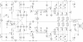
I started drawing up the schematic and made a few changes: adding decoupling caps on each output power transistor, moving the zobel to the speaker side of the output R//L, adding diodes on the output, making the 3 parallel caps on the grounded side of the feedback in only one non polarized cap (2.2uF instead of the 3 x 820nF).
I looked at the R11 and R12 and thought I should verify for wattage, and sure enough, an ordinary 1/4 or 1/2watt resistor would be heating too much, so I put 1W resistors there.
I think it might not be luxury to add decoupling caps as well on the other sides of R11 & R12 on the current sources, that is in addition to those 47u filters on the zeners.
There is a fair number of transistors, however most of them are TO92 cases, and they're cheap, so that shouldn't be a cause for concern on cost, and the power transistors can all be fitted on one big heatsink, TO3s and TO126s.
Elektor mentions thermally coupling T9 to T11 and T10 to T12, which I indicated on the sch. If this works, it's much easier than trying to thermally couple 2 TO92s to the main heatsink.
Now I left out the connections between the transistors in the 3 last stages, since I provided for 3 pairs of 3055s, those need to be connected in the right way and if possible let's try to keep it as symetric as possible.
So can anyone pitch in and help finish those connections?
Any comments on what's been done so far?
Then we'll have to look at making this a "high side" of a grounded bridge, by making a "low side" properly. Which may be a bit different from the high side.
It will be tricky to make a proper pcb layout with 6 pairs of TO3s on one heatsink, and try to avoid any wiring. I think in view of the potential extra complexity in the grounded bridge setup, a diy module should be as bullet proof as possible and avoid as much wiring as possible.
I'd like to arrive at something that can be assembled just like any diy kit, and that it would work the first time without any difficulty. A bit of a tall order!
Making a double-sided plated through pcb that can be made by a board house, although perhaps a little more pricy, can make for a solid base that can be easily built fast even by a diy beginner.
Schematic attached, please help...
Those who built it mostly are reporting a stable, robust and good sounding amp. Plus I like that symetry, which would be nice to preserve as much as possible.
I started drawing up the schematic and made a few changes: adding decoupling caps on each output power transistor, moving the zobel to the speaker side of the output R//L, adding diodes on the output, making the 3 parallel caps on the grounded side of the feedback in only one non polarized cap (2.2uF instead of the 3 x 820nF).
I looked at the R11 and R12 and thought I should verify for wattage, and sure enough, an ordinary 1/4 or 1/2watt resistor would be heating too much, so I put 1W resistors there.
I think it might not be luxury to add decoupling caps as well on the other sides of R11 & R12 on the current sources, that is in addition to those 47u filters on the zeners.
There is a fair number of transistors, however most of them are TO92 cases, and they're cheap, so that shouldn't be a cause for concern on cost, and the power transistors can all be fitted on one big heatsink, TO3s and TO126s.
Elektor mentions thermally coupling T9 to T11 and T10 to T12, which I indicated on the sch. If this works, it's much easier than trying to thermally couple 2 TO92s to the main heatsink.
Now I left out the connections between the transistors in the 3 last stages, since I provided for 3 pairs of 3055s, those need to be connected in the right way and if possible let's try to keep it as symetric as possible.
So can anyone pitch in and help finish those connections?
Any comments on what's been done so far?
Then we'll have to look at making this a "high side" of a grounded bridge, by making a "low side" properly. Which may be a bit different from the high side.
It will be tricky to make a proper pcb layout with 6 pairs of TO3s on one heatsink, and try to avoid any wiring. I think in view of the potential extra complexity in the grounded bridge setup, a diy module should be as bullet proof as possible and avoid as much wiring as possible.
I'd like to arrive at something that can be assembled just like any diy kit, and that it would work the first time without any difficulty. A bit of a tall order!
Making a double-sided plated through pcb that can be made by a board house, although perhaps a little more pricy, can make for a solid base that can be easily built fast even by a diy beginner.
Schematic attached, please help...
Attachments

Here is a sch update. I documented some things, completed it a little more and also made a few changes that I think are improvements. Go ahead with comments on that.
Having made those changes, it changes the gain on the input stage and I think some calculations are in order to make sure the main feedback is correct.
One other thing I'm wondering about, is that input filter's cut off frequency and if it really needs to be that complicated. It seems to be to have been made for a steeper roll off. Does it really need this? Couldn't we just simplify this with a single cap and res??
Attachments
The input filter looks fine...
Feedback capacitor is a bit low at 2.2uF. It cuts into the low frequency response.
I would drop the zeners+caps in the input ccs in favor of just leds. Save a bit of space and works just as well.
Feedback capacitor is a bit low at 2.2uF. It cuts into the low frequency response.
I would drop the zeners+caps in the input ccs in favor of just leds. Save a bit of space and works just as well.
I would drop the zeners+caps in the input ccs in favor of just leds. Save a bit of space and works just as well.
+1. You do not want to waste a 5V drop in the CCS if you end up using this amp in a grounded bridge. I would simply use the 2-transistor CCS which works down to 2Vbe. Remember, the rails will be moving, and the diff pairs need to common-mode all the way to the rail or as close to it as possible. For this reason, the traditional diff pair input is not preferred. Not saying it won't work, but you will pay a couple volts penalty in output swing that you don't absolutely have to. You would get better results if the input stage runs off its own stabilized supply that is referenced to the artificial ground produced by the low side amp. The QSC circuit does this for its op amps.
Feedback capacitor is a bit low at 2.2uF. It cuts into the low frequency response.
Elektor's initial value was 3 caps of 820n each, so using 2.2uF did make the value a little lower, but not that much. I tried calculating the frequency using R*C=1/(2 Pi fc) and found a -3db around 15Hz. Am I using the right formula? Using R4 for R and C3 for C.
If we go to 10uF, I calculate this at a bit less than 3.5Hz, if I'm calculating it right. Would that work better?
I would drop the zeners+caps in the input ccs in favor of just leds. Save a bit of space and works just as well.
That's a little superfluous, but if space becomes an issue during layout, that could be considered. Although it may remove a zener and cap, it still requires a resistor to set the current and that current would be a little higher than with the zeners I think, which may even require a bigger resistor than the current 1W.
No comments on using those base and emitter resistors on the diff amp?
What about those base resistors on all the 3055s??
The BD139/140 may have a tougher job driving so many 3055s, especially when on a 2ohms load.
- Home
- Amplifiers
- Solid State
- Amplifier based on 2N3055