Though I do not understand why this would be I understand what to do now. Thanks again for explaining. So I will get different resistors and see if R4 current then will be closer to 1.2V.
With the 27R resistor the proper voltage across R4 would be closer to 0.25-0.3V, as we are measuring voltage across a resistance to compute the current. Because the resistor value is changing, but the target current (10mA) is the same, the voltage drop across the resistor must be different.
0.3V measured across 27R is 11mA (.3/27= 0.011) and 11mA is still fine and will let us know if the existing too-low current is the issue in sound.
Thanks for explaining. So as I changed the R4s to 27 Ohms I will measure voltage again and post here?
I have seen my resistors are all 0.5W, does it matter if that value is different, let's say 0.25W, 0.6" or 1W?
I've ordered one of these recently available PCB's and have started putting together orders for the components to build it. As this is my second DIY Kit I have a few questions that I've been unable to google for so far.
The PDF lists Q5,6 as IRFP610. Outside of that doc and this forum I can find virtually no reference to this part. I think it may be the same as the IRF610? Can I use a Vishay IRF610PBF or similar? If not where can I find IRFP610 parts for sale?
C5 is a 33PF Capacitor in a rectangular form factor. I don't know enough about parts to have any idea what to order, can anyone advise on this or suggest a specific part number please?
IRFP610 was a typo. IRF610PBF is good. PBF stands for lead free and that is what is available as the non-PBF IRF610 are now obsolete.
Choose a 33pF film cap. Here is one:
https://www.mouser.com/ProductDetai...EpiMZZMukHu%2BjC5l7Ya09z%2BPFYd21tjAO0570ANE=
Choose a 33pF film cap. Here is one:
https://www.mouser.com/ProductDetai...EpiMZZMukHu%2BjC5l7Ya09z%2BPFYd21tjAO0570ANE=
JamesHH,
Please note that R4 may need adjustment, depending on the J113 (Q3) that you receive. There are variations in the properties of the J113. You will not know whether the R4 value of 125R will be OK until after testing in-circuit or during testing before installing.
See this post Amp Camp Pre+Headphone Amp - ACP+ and following posts , and also here: Amp Camp Pre+Headphone Amp - ACP+.
R4 may need to be as low as 36R. So if you do not have easy local access to resistors, then you should order an assortment of resistors between 125R and 36R, say in increments of 10R or so. You will need two of each (one per channel).
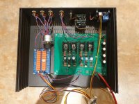
My ACP+ is mostly completed now. I’ve used a relay based potentiometer and the amount of detail is exceptional. I checked everything worked before putting it in the case and it was absolutely silent with a Meanwell SMPS. Now I have it in the case, I have noticed a faint mum that increases as the volume goes up.
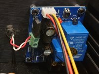
I have tracked it down to the ‘digital’ earth of the relay control section of the pre-amp. It reads 11.9V ac and approximately 9μA ac. I can ‘cure’ the hum by connecting the ‘digital’ earth directly to the case but I prefer prevention rather than cure. Does have anyone have experience of a similar problem?
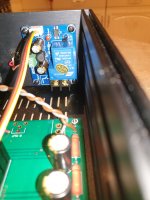
The only AC in the case is the red and white wires on the right hand rear corner from a separate 12Vac wall wart which is there to supply the volume control section. After that it is rectified to 5Vdc.
Pictures will follow shortly.
I have tracked it down to the ‘digital’ earth of the relay control section of the pre-amp. It reads 11.9V ac and approximately 9μA ac. I can ‘cure’ the hum by connecting the ‘digital’ earth directly to the case but I prefer prevention rather than cure. Does have anyone have experience of a similar problem?
The only AC in the case is the red and white wires on the right hand rear corner from a separate 12Vac wall wart which is there to supply the volume control section. After that it is rectified to 5Vdc.
Pictures will follow shortly.
Oh no!
I just ordered a board, and forgot to order the jfets! And it's already been shipped!
Anyone in Australia have some spares they want to sell me? Saves having to pay shipping on another order? I've already got some spare j113s from a 6-24 build.
I just ordered a board, and forgot to order the jfets! And it's already been shipped!
Anyone in Australia have some spares they want to sell me? Saves having to pay shipping on another order? I've already got some spare j113s from a 6-24 build.
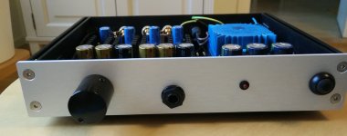
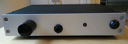
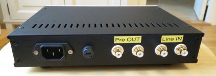
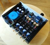
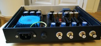
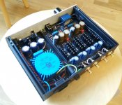
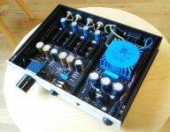
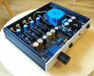
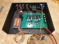
I guess I need to post few pictures to thank Nelson and everyone here to let me start over (after ~10 years missing from these pages) with such a nice project.
Bad pictures I know... I invested in this project rather than in a new phone with a better camera. 🙂
The PCB design is by withmatt (post #341) and I got it from iamwhoiam (post #397). I used axial capacitor in C1 and the LM317L as current source as for withmatt suggestion since I couldn't find a match with the J113/resistors I got. The PCB has space for a trimmer in the R4 position and maybe I will play with it in the future.
PCB for PSU is by Gaz2613 but it is the older version of the one you see in post #949.
A big thanks everyone!
Attachments
-
 2020-12-03 09.52.46.jpg280 KB · Views: 406
 -
 2020-12-03 10.11.12.jpg219.1 KB · Views: 220
 -
 2020-12-03 10.10.37.jpg277.5 KB · Views: 236
 -
 2020-12-03 09.54.35.jpg477.9 KB · Views: 240
 -
 2020-12-03 09.54.18.jpg381 KB · Views: 379
 -
 2020-12-03 09.54.10.jpg459.8 KB · Views: 378
 -
 2020-12-03 09.53.52.jpg418.9 KB · Views: 405
 -
 2020-12-03 09.53.34.jpg398 KB · Views: 424
Last edited:


Peppe and SuppersReady -
Beautiful builds. Love the personally chosen tweaks and mods to each. Congratulations!

Beautiful builds. Love the personally chosen tweaks and mods to each. Congratulations!
Thanks ItsAllInMyHead.
Pepper, nice work with yours. Very impressed with how tidy it is.
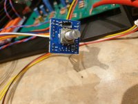
The interconnections for the relay controls will be trimmed to fit once the case is fully finished. The selector switch will get an extension rod too. The extra benefit of this potentiometer kit is that volume is also remote controlled. If I can solve the hum issue I'll be much happier.
Pepper, nice work with yours. Very impressed with how tidy it is.
The interconnections for the relay controls will be trimmed to fit once the case is fully finished. The selector switch will get an extension rod too. The extra benefit of this potentiometer kit is that volume is also remote controlled. If I can solve the hum issue I'll be much happier.
Pictures as promised.
Is your relay PSU using a virtual ground or some other arrangement to produce a bipolar supply? If so, it may be an issue if the barrel connector jack is not isolated from the chassis. Or at least this has been something I’ve dealt with in the past.
Is your relay PSU using a virtual ground or some other arrangement to produce a bipolar supply? If so, it may be an issue if the barrel connector jack is not isolated from the chassis. Or at least this has been something I’ve dealt with in the past.
Agreed. An easy check would be to remove the volume control power input connector from the chassis and just let it dangle outside. Power up everything and see if hum is gone.
Thanks for the nice words. 😱
This was a "dense" build since I want to easily carry it around for headphone use. If there will be a new build I shall go with more features as in SuppersReady example since I found out how good it is as pre. 😱
This was a "dense" build since I want to easily carry it around for headphone use. If there will be a new build I shall go with more features as in SuppersReady example since I found out how good it is as pre. 😱
Agreed. An easy check would be to remove the volume control power input connector from the chassis and just let it dangle outside. Power up everything and see if hum is gone.
Cisco and codyt,
I've used a plastic bodied connector for ac line but kept a metal bodied one for the dc line.
Cisco and codyt,
I've used a plastic bodied connector for ac line but kept a metal bodied one for the dc line.
That's good.
Hmm... On that potentiometer relay board, do they have the relay ground tied to the audio ground? The relay coil is isolated from the relay contacts, in the relay itself. It's the next thing to look at.
... Now I have it in the case, I have noticed a faint mum that increases as the volume goes up.
I have tracked it down to the ‘digital’ earth of the relay control section of the pre-amp. It reads 11.9V ac and approximately 9μA ac. I can ‘cure’ the hum by connecting the ‘digital’ earth directly to the case but I prefer prevention rather than cure. Does have anyone have experience of a similar problem?
The only AC in the case is the red and white wires on the right hand rear corner from a separate 12Vac wall wart which is there to supply the volume control section. After that it is rectified to 5Vdc.
Pictures will follow shortly.
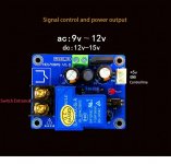
I found this pic of that input module. Could feed it with 12 VDC, that would quiet the ground. You might have to experiment with the polarity depending on how they connected grounds.
Attachments
With the 27R resistor the proper voltage across R4 would be closer to 0.25-0.3V, as we are measuring voltage across a resistance to compute the current. Because the resistor value is changing, but the target current (10mA) is the same, the voltage drop across the resistor must be different.
0.3V measured across 27R is 11mA (.3/27= 0.011) and 11mA is still fine and will let us know if the existing too-low current is the issue in sound.
I have changed R4s to 27 Ohms (across R4 roughly 325mV now) and it seems to be better. First impression is good! Thank you! Is it also an option to change the caps for smoother high frequencies? Which ones would I change in this case?
- Home
- Amplifiers
- Pass Labs
- Amp Camp Pre+Headphone Amp - ACP+