Yes it does have a lot of filtering right on the board! Nelson designed it to be used with the SMPS.
Well done! I wouldn’t feel obligated to go all out on a power supply. There’s a good amount of filtering on the board to accommodate simple wall wart switchers.
The onboard filter is really good, looking at the rail on a scope from the front of the filter to the end is surprising. (I need to get some photos of that...) It does a very good job and erases an incredible amount junk from the wall wart.
Also, it’s worth mentioning that the wall warts are getting better and better over time. Particularly MeanWell.
That said, Mark’s filters are next level, and I can wholeheartedly and enthusiastically recommend them for anything powered by a SMPS wart.
Also, it’s worth mentioning that the wall warts are getting better and better over time. Particularly MeanWell.
That said, Mark’s filters are next level, and I can wholeheartedly and enthusiastically recommend them for anything powered by a SMPS wart.
You could also use a 200R trimpot in place of R4 temporarily. I did this, and put them in sockets so I could remove them easily to measure the resistance as I got closer to the optimal value. To any newbs reading this, you’ll want to remove the trimpot and sockets and replace them with a fixed resistor once you figure out the right value of R4 to give 10ma through R4.
FWIW, I ended up at 40R on one channel and 45R on the other. I started at 125R and was only getting something like 4ma. But your experience may vary of course.
Apologies for the noob question:
To measure "10mA through R4" - should I use my multi-meter in DC current mode, and touch the 2 leads of R4 to measure the amount of current though it?
To measure current through a resistor, put the multimeter in DC voltage mode and measure the voltage with the probes on each side of the resistor. Then use Ohm's Law, V=IR which gives I=V/R.
For instance if R=125 Ohm and V=1.1V,
then I=1.1V/125R=0.0088A or 8.8mA.
For instance if R=125 Ohm and V=1.1V,
then I=1.1V/125R=0.0088A or 8.8mA.
Apologies for the noob question:
To measure "10mA through R4" - should I use my multi-meter in DC current mode, and touch the 2 leads of R4 to measure the amount of current though it?
To measure current through a resistor, put the multimeter in DC voltage mode and measure the voltage with the probes on each side of the resistor. Then use Ohm's Law, V=IR which gives I=V/R.
For instance if R=125 Ohm and V=1.1V,
then I=1.1V/125R=0.0088A or 8.8mA.
Thanks Ben!
If I still want to use the DC current on my DMM - can I connect only 1 of the R4 leads to the PCB, and the DMM between the 2nd lead and its PCB connections (in serial)? Would that allow to measure (as opposed to calculate) the actual current? Does it matter WHICH of the 2 leads of R4?
I am trying to learn things out of this project, not just "have it work" 😉
You can theoretically measure current by unsoldering one lead of the resistor and putting the meter in series. However it is easier to measure voltage and calculate the current, and less wear and tear on the board and resistor. I am also not sure how accurate a meter is at milliAmp level of current.
I am not sure what you mean by "WHICH of the 2 leads of R4"? A resistor only has two ends, so one meter probe at each end of the resistor. However there are two channels so you should be measuring both channels.
Ok, I think I understand your question. If you want to unsolder one end of the resistor, it does not matter which end. However I recommend measuring the voltage across the resistor method.
Last edited:
Ok, I think I understand your question. If you want to unsolder one end of the resistor, it does not matter which end. However I recommend measuring the voltage across the resistor method.
Yup, you got my question! 🙂
I will follow your advice and measure voltage and calculate. Did not think about the "problem" that my DMM is probably not accurate enough for measuring fractions of 1mA...
Today, I am going to go through the process of matching the J113 JFETS. I will go through the process discussed earlier in this thread (post #697 but with the correct pinout). Let me make sure I understand the process correctly:
1. Find 2 JFETs that measure the same (or very very close) voltage with the same R value (say 125 Ohm).
2. Find a resistor that for these specific J113s would measure 1.2V (1/10 of my supply voltage of 12V) - that would mean the current is 10mA as desired.
Did I get it right?
Does it mean that in the ACP+ they would also provide 10mA (using same R value for R4 as the one in step 2 above)? or would the resulting current in ACP+ be different due to different voltage levels? My source is a variable power source, so I could use ANY voltage up to 32V... Does not have to be 12V if that is not representative of what happens in the ACP+ later.
Thanks again - I am learning A LOT from this little project!!! 🙂
1. Yes, and use 12V for V+.
2. Again, use 12V. If the voltage measured from 1. gave a current lower than 10mA, replace the resistor with one of lower value, measure the voltage drop and recalculate. If the voltage measured from 1. gave a current higher than 10mA, replace the resistor with one of higher value, measure and recalculate. You may need to do this multiple times to close in on the proper resistor value.
Use the resistor value that was determined in 2. for R4 on the board. The voltage seen by the J113 on the board is approximately 12V so the resistor value should be correct. Once installed and the board is operational, you can measure the voltage across R4 to confirm the 10mA current.
Note that the current doesn't have to be exactly 10.00mA. A bit less or a bit more is okay as long as both channels are matched.
Something does not make sense here... 🙁
I have 10 x J113 so measured voltage on 125 ohm resistor for each and every one (connected to a breadboard). Powered by 12V power supply.
Voltages range between 0.67V and 0.80V. OK.
Now, I replaced the 125 ohm with a 100 ohm resistor, for 1 of the J113s, and saw:
* With 125 ohm: 0.77V
* With 100 ohm: 0.70V
I expected the voltage to go UP with lower R... not down!!!
What am I missing?!
What was the error in the RCA jacks that were specified previously?
I have already used your previous BOM as a starting point for my component order (I got most of the components already...).
They are the right make - they fit the board - they were just the wrong color. The change was to include white and red ones for left and right channels. I just built most of a prototype with the yellow ones and all is well, so feel free to use them if you have those just find a way to label L and R. 🙂
--Tom
Something does not make sense here... 🙁
* With 125 ohm: 0.77V
* With 100 ohm: 0.70V
I expected the voltage to go UP with lower R... not down!!!
What am I missing?!
0.77V/125R=6.2mA
0.70V/100R=7.0mA
You are missing reading comprehension. See my previous post. Gotta do the math.🙂
Lower the resistance again.
Last edited:
Something does not make sense here... 🙁
I have 10 x J113 so measured voltage on 125 ohm resistor for each and every one (connected to a breadboard). Powered by 12V power supply.
Voltages range between 0.67V and 0.80V. OK.
Now, I replaced the 125 ohm with a 100 ohm resistor, for 1 of the J113s, and saw:
* With 125 ohm: 0.77V
* With 100 ohm: 0.70V
I expected the voltage to go UP with lower R... not down!!!
What am I missing?!
To measure current through a resistor, put the multimeter in DC voltage mode and measure the voltage with the probes on each side of the resistor. Then use Ohm's Law, V=IR which gives I=V/R.
For instance if R=125 Ohm and V=1.1V,
then I=1.1V/125R=0.0088A or 8.8mA.
Wait! Let me try again... 😉
R = 125, V=0.77 ==> I=V/R = 0.77/125 = 6.16mA
R = 100, V=0.70 ==> I=V/R = 0.70/100 = 7mA
So... lower R did in fact gave me higher current. Right? 🙂
So how do I extrapolate the needed R (since V changes when I change R)??
or is there no way other than keep trying R values lower than 100?
Edit: Ben - I was typing as you were posting 😉 Thanks for confirming my findings!!
Gotta keeping going lower in value. You’re measuring less voltage only across the resistor. Less resistance, so more is getting through (instead of dropping across the resistor). I ended up around 60R, as an example
For instance, if you attached both clips to a plain wire with voltage, you’d expect a reading of 0v
Gotta keeping going lower in value. You’re measuring less voltage only across the resistor. Less resistance, so more is getting through (instead of dropping across the resistor). I ended up around 60R, as an example
Got it. I do not have on hand more <100R resistors at the moment, but getting a big multi-value assortment from Amazon tomorrow. Below 100R, it should have:
91R, 82R, 75R, 68R, 62R, 56R, 51R, 47R, 43R, 39R, ...
Hopefully, one of those would be very close to 10mA 😉
How important for R4 to be 1/2W?
The collection from Amazon is 1/4W resistors. Worst case, after I discover the correct value - I could buy 1/2W of that value!
I think 1/4 watt should be fine. If you really want to get it done today, You can parallel your 100R with some other value to get a lower overall value. For instance, piggy backing a 100R with another 100R would get you 50R
Zachik,
Power = V x I
Since also V= I x R, which you used for calculating the current through the resistor,
Power = I x R x I = I^2 x R
So for 100R resistor and 10mA, Power = (0.010A)^2 x 100R= 0.01W
And for values lower than 100R, the power dissipation at 10mA is even less.
Resistors are usually sized for a minimum of twice their anticipated power dissipation to keep their temperature at a reasonable level.
So 1/4W for a dissipation of 0.01W is good.
Zachik,
Power = V x I
Since also V= I x R, which you used for calculating the current through the resistor,
Power = I x R x I = I^2 x R
So for 100R resistor and 10mA, Power = (0.010A)^2 x 100R= 0.01W
And for values lower than 100R, the power dissipation at 10mA is even less.
Resistors are usually sized for a minimum of twice their anticipated power dissipation to keep their temperature at a reasonable level.
So 1/4W for a dissipation of 0.01W is good.
Thanks Ben!!!


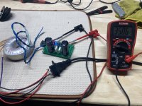
Question regarding building this with a linear power supply. I posted earlier about using a CapMX multiplier board with transformer that I usually use on my Amp camp builds. I bought a 24V secondary transformer and tested it on my CapMX power supply today and the rail voltage was 35V. I understand it will sag once I add in the ACP, but any harm in the ACP having higher voltages as I don’t see the voltage sagging enough to get down to 24V?
Below is a pic of the CapMX with the voltage reading.
Below is a pic of the CapMX with the voltage reading.
Attachments
Last edited:
- Home
- Amplifiers
- Pass Labs
- Amp Camp Pre+Headphone Amp - ACP+