Great tester
Listen to 6L6, he is right, it's a very good tester. It will even tell you the correct drain , source, gate lead orentation on those JFETS.
Any MEGA328 tool is fantastic, you will wonder how you lived without it!!!
Listen to 6L6, he is right, it's a very good tester. It will even tell you the correct drain , source, gate lead orentation on those JFETS.
I seldom stuff a part without checking it on the MEGA328. It has saved me several diodes/transistors being installed backwards.
Any MEGA328 tool is fantastic, you will wonder how you lived without it!!!
I love mine, but every time I use it I remember when I taught the difference between precision and accuracy in freshman Physics lab.
Took mine to work for a show and tell, there may be a world shortage soon, so many of the other techs are going to buy them.
I love mine, but every time I use it I remember when I taught the difference between precision and accuracy in freshman Physics lab.
Ahh haha yes I too always remember that lesson when using cheap DMMs, digital thermometers, etc. The curse of the OCD engineer/DIYer’s mind.
I’m curious if anyone has compared Mega328 results side-by-side with a higher end LCR meter or transistor tester.
I guess it’s usually close matching between multiple components we’re after in DIY audio, more often than knowing the exact correct values. In that case, you want precision first, accuracy second. I of course haven’t tested this theory but if I were a betting man, I would guess that’s what the Mega328 delivers. Precision, but maybe not accuracy.
Last edited:
The main advantage of the DCA75 pro over those simple transistor testers is, that it is a (small signal) curve tracer when connected to a pc via USB.
to nr12
I fully agree with you!
The main advantage of the PEAK DCA75Pro is the possibilty to match transistors.
I f you don't need it.... the Mega328 is a nice tool
Greets
from a 'swabian' to a 'swabian' 😀
Dirk
I fully agree with you!
The main advantage of the PEAK DCA75Pro is the possibilty to match transistors.
I f you don't need it.... the Mega328 is a nice tool
Greets
from a 'swabian' to a 'swabian' 😀
Dirk
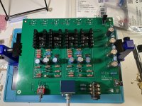
6L6 built a prototype from the BOM we posted a little while back and found an error in the RCA jacks that were specified, so I've updated the BOM and you can find that below.
What was the error in the RCA jacks that were specified previously?
I have already used your previous BOM as a starting point for my component order (I got most of the components already...).
The DCR75pro can.
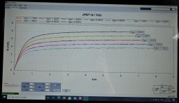
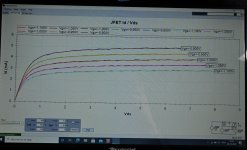
The two images shows two pairs I checked after matching Vgs/Ids at Ids = 3mA (for M2X IPS#6 boards).
The two J113 in each pair follows more of less the same curve.
So it is a two step procedure. First I measure like 50-100 J113 and write down at which Vgs I measure 3mA (at the higest Vds possible with the tool which was a bit lower than the real working condition). 3mA is the working condition for the J113 in IPS#6 boards. After this I group the J113 after Vgs and I find some pairs that could be a candidate for at "real" pair. The candidates I check making a curve trace to see how close they follows each other.
For the Ids = 3mA measurement I use the Ids vs Vgs curve (it is good to set like 100 test points and have the Vgs range as close as possible to where the device has Ids = 3mA to get a good Vgs value where Ids is 3mA. This range can change from device to device.
The correct range for Vgs has to be set and there is also a possibility to lock the range setting etc. There is a small learning curve for using the tool.
Attachments
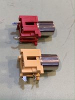
Zachik - the BOM originally had the PCB mount RCA jacks with the terminals in the wrong location.
In the photo the red one has the solder tabs in the back, this is wrong, the yellow has the tabs on the bottom, which is proper.
CUI RCJ-04x series will fit the board. The final digit “x” defines the color.
In the photo the red one has the solder tabs in the back, this is wrong, the yellow has the tabs on the bottom, which is proper.
CUI RCJ-04x series will fit the board. The final digit “x” defines the color.
Attachments
and what I'm always saying about BOMs ........ make your own!
besides learning on own mistakes, you're actually learning
asking for help while making your own BOM is normal and welcome thing
🙂
besides learning on own mistakes, you're actually learning
asking for help while making your own BOM is normal and welcome thing
🙂
ZM is 100% right. 
The RCA part number on Nelson’s article is correct. It got messed up on the BOM posted in post #659, but has since been corrected.
The RCA part number on Nelson’s article is correct. It got messed up on the BOM posted in post #659, but has since been corrected.
Zachik - the BOM originally had the PCB mount RCA jacks with the terminals in the wrong location.
In the photo the red one has the solder tabs in the back, this is wrong, the yellow has the tabs on the bottom, which is proper.
CUI RCJ-04x series will fit the board. The final digit “x” defines the color.
and what I'm always saying about BOMs ........ make your own!
besides learning on own mistakes, you're actually learning
asking for help while making your own BOM is normal and welcome thing
🙂
6L6 - Got it. Thanks.
ZM - I DID make my own BOM, but used the BOM posted here as a starting point / reference. I replaced several components, and the RCAs in my case are panel mounted (used the ones recommended by 6L6 on a separate PM, to match those of the ACA kit...)
The DCR75pro can.
The two images shows two pairs I checked after matching Vgs/Ids at Ids = 3mA (for M2X IPS#6 boards).
The two J113 in each pair follows more of less the same curve.
So it is a two step procedure. First I measure like 50-100 J113 and write down at which Vgs I measure 3mA (at the higest Vds possible with the tool which was a bit lower than the real working condition). 3mA is the working condition for the J113 in IPS#6 boards. After this I group the J113 after Vgs and I find some pairs that could be a candidate for at "real" pair. The candidates I check making a curve trace to see how close they follows each other.
For the Ids = 3mA measurement I use the Ids vs Vgs curve (it is good to set like 100 test points and have the Vgs range as close as possible to where the device has Ids = 3mA to get a good Vgs value where Ids is 3mA. This range can change from device to device.
The correct range for Vgs has to be set and there is also a possibility to lock the range setting etc. There is a small learning curve for using the tool.
I assume you're referring to this one?
https://www.amazon.com/Atlas-ADVANCED-SEMICONDUCTOR-ANALYZER-Tracing/dp/B00O0BMNX2/
Already invested $350-400 in equipment in the last 2 weeks, what's $160 more? 😱
For anyone in the UK that ordered the wrong rca connectors and doesn’t have a large order for digikey etc to qualify for free shipping (it’s £12 for £6 worth of parts) I found some equivalents on eBay that come in at £1 each when I ordered 6. The item number is 193161229522...they come in red and white. The pins are in line but at 4.5mm spacing look like they will fit the holes on the board.
I assume you're referring to this one?
https://www.amazon.com/Atlas-ADVANCED-SEMICONDUCTOR-ANALYZER-Tracing/dp/B00O0BMNX2/
Already invested $350-400 in equipment in the last 2 weeks, what's $160 more? 😱
Yes, that is the one.
I got my directly from Peak in UK:
Peak Atlas DCA Pro model DCA75 | Peak Electronic Design Limited
.....but since you are located in US Amazon is better.
They have a good technical support.
Already invested $350-400 in equipment in the last 2 weeks, what's $160 more? 😱
That totally depends on how much more you intend to build...
That said, I have zero issues spending money on good tools. Money well spent.
- Home
- Amplifiers
- Pass Labs
- Amp Camp Pre+Headphone Amp - ACP+