Oh yes. I realized I probably don’t have connection between the whole chassis and I didn’t remove any paint where the standoffs connect to chassis. Should both the Korg and ACP be done the same? Both have the same low level hum.
I basically built both units the same but might need to sand the corners where the screws attach panels.
I’m using triad SMPS. I believe the WSU-24V 500ma
I basically built both units the same but might need to sand the corners where the screws attach panels.
I’m using triad SMPS. I believe the WSU-24V 500ma
Attachments
O
i used a knife to remove anodization. No patience. Looks like crap, but the screws hide it, my ears don’t care.
again, a nice build of yours 🙂
ps: did you use the same PSU for both preamps? That is a common denominator, along with possible chassis contact issues.
also, and I don’t know if this is relevant, ensure dc inlet is soldered at the correct places. I kinda struggled finding them. Damn greenhorns (me)
(me)
regards,
Andy
Yes. Both those preamps have the same gnd scheme from pcb to chassis. I had increased background noise, yanno, in the khz range, not hum, before removing anodization around the pot bolt hole in my black front plate. Haven’t had any hum though.Oh yes. I realized I probably don’t have connection between the whole chassis and I didn’t remove any paint where the standoffs connect to chassis. Should both the Korg and ACP be done the same? Both have the same low level hum.
I basically built both units the same but might need to sand the corners where the screws attach panels.
I’m using triad SMPS. I believe the WSU-24V 500ma
i used a knife to remove anodization. No patience. Looks like crap, but the screws hide it, my ears don’t care.
again, a nice build of yours 🙂
ps: did you use the same PSU for both preamps? That is a common denominator, along with possible chassis contact issues.
also, and I don’t know if this is relevant, ensure dc inlet is soldered at the correct places. I kinda struggled finding them. Damn greenhorns
(me)regards,
Andy
The key is keeping your return paths (including on the I/O) going to the same point (ala star grounding) and then to the chassis earth ground via at a minimum, what Papa calls "a little resistance" (hence the CL-60). Like with the Whammy, all of the RCAs' negatives are connected together and then to ground via the cap. The same for the volume pot, which should have a ground point. This also applies to the chassis, which are typically made from a number of modular panels that might be painted or anodized which are non-conductive or if scratched/thin could be partially conductive. For these, sand off the paint/anodizing from the mating surfaces by using some high grid sand paper (or those 3M scrubby pads) so you have solid continuity. Then TEST your continuity using your Ohm/continuity setting on your DVM. Probe around across all points with the negative set on the earth.Can someone recommend an easy ground loop breaker for this unit? I built one into a chassis and having some low level hum. Same problem on my Korg B1 in the same chassis.
Could I attach a .47uf film cap to ground just like the Whammy?
I currently don’t have a spare CL-60 on me.
For a complete solution for how to attach the star ground to the chassis earth that you'll find in commercial products, you really need a 3-way parallel path of a diode bridge, cap and resistor to handle all the cases. These all need to be rated for a min of the line rate voltage you will be using to be properly compliant to the various codes although its pretty easy and not much more expensive to get 600V-rated components. There is a subthread on the Whammy project where Wayne chimes in about this. I've personally been using these for a long while. They are neat and tidy/compact, reasonably priced and just work: Broskie's products are top-notch quality and designs.
https://glass-ware.stores.yahoo.net/housegnd.html

Are you sure the stand-offs are connected to the return path on the B1k's board? Use your DVM and check...Oh yes. I realized I probably don’t have connection between the whole chassis and I didn’t remove any paint where the standoffs connect to chassis. Should both the Korg and ACP be done the same? Both have the same low level hum.
I basically built both units the same but might need to sand the corners where the screws attach panels.
I’m using triad SMPS. I believe the WSU-24V 500ma
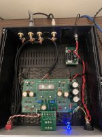
Working on the ACP now. I realized I didn’t have any continuation from the standoffs to the back of the chassis.
I sanded off some of the anodized black around the back top-right screw and ran a wire from the back standoff to this location.
The hum is quieter but still noticeable with the horned speakers I am using. I will try sanding off some more anodizing on each stand-off.
any idea how to connect the bottom plate of the Galaxy to the sides and top? Doesn’t appear the top and bottoms are connected right.
Please post high-res pictures so we can help you.Working on the ACP now. I realized I didn’t have any continuation from the standoffs to the back of the chassis.
I sanded off some of the anodized black around the back top-right screw and ran a wire from the back standoff to this location.
The hum is quieter but still noticeable with the horned speakers I am using. I will try sanding off some more anodizing on each stand-off.
any idea how to connect the bottom plate of the Galaxy to the sides and top? Doesn’t appear the top and bottoms are connected right.
I added the wire to be sure the sides are connected. I also sanded down one standoff underneath and sanded to get a good connecting between the top and sides.

I just re-read your post and it is not obvious so to be clear, are you using the ground plane board or avoiding that and trying to use just the main board with a chassis?Please post high-res pictures so we can help you.
as I said - just be sure that all screws are tight....
any idea how to connect the bottom plate of the Galaxy to the sides and top? Doesn’t appear the top and bottoms are connected right.
it is usually enough - confirm contact of all panels with ohmmeter
also , check that front metal part of volume pot body is in contact with case
I added the wire to be sure the sides are connected. I also sanded down one standoff underneath and sanded to get a good connecting between the top and sides.
You shouldn't have to use any extra bonding as you are doing. If not done correctly can actually make things worse. Simply sanding the anodizing off the mating surfaces should be sufficient. Make sure the under sides of the top/bottom where they touch the chassis are also sanded off as the screws/nuts might not make solid contact. But again, test with your ohm meter to ensure solid continuity all around the chassis and back to the - on the DC inlet. I've built a bunch of these now and the only issues I've ever had are around making the chassis continuous as well as sometimes having to add an explicit bonding wire for the volume pot from its ground point/case, which manifests itself as audible low hum or you can measure this with a scope and look for 60hz/harmonics. If you don't have a scope/etc... to measure, use your ears as you connect the ground lug on the pot or move around the top/bottom but even a $20 multimeter's OHM setting can do this. Re-reading the thread above, this is what sounds like your issue.
I've read up the thread and just realized you have external DC input to your B1K and not AC, so you shouldn't need the ground isolator I suggested above. All you should need for the B1K is solid chassis and volume potentiometer continuity to keep things quiet, at least for 60Hz-type hum.The key is keeping your return paths (including on the I/O) going to the same point (ala star grounding) and then to the chassis earth ground via at a minimum, what Papa calls "a little resistance" (hence the CL-60). Like with the Whammy, all of the RCAs' negatives are connected together and then to ground via the cap. The same for the volume pot, which should have a ground point. This also applies to the chassis, which are typically made from a number of modular panels that might be painted or anodized which are non-conductive or if scratched/thin could be partially conductive. For these, sand off the paint/anodizing from the mating surfaces by using some high grid sand paper (or those 3M scrubby pads) so you have solid continuity. Then TEST your continuity using your Ohm/continuity setting on your DVM. Probe around across all points with the negative set on the earth.
For a complete solution for how to attach the star ground to the chassis earth that you'll find in commercial products, you really need a 3-way parallel path of a diode bridge, cap and resistor to handle all the cases. These all need to be rated for a min of the line rate voltage you will be using to be properly compliant to the various codes although its pretty easy and not much more expensive to get 600V-rated components. There is a subthread on the Whammy project where Wayne chimes in about this. I've personally been using these for a long while. They are neat and tidy/compact, reasonably priced and just work: Broskie's products are top-notch quality and designs.
https://glass-ware.stores.yahoo.net/housegnd.html
Quick update, I was able to confirm continuity in the ACP chassis and the hum is lower than it was before but it’s still there. Since the speakers are horn loaded I can barely hear the hum unless I am 1 inch from the woofer, but when I step away the hum comint out the back horn opening is slightly noticeable from center position a couple feet away.
One thing I realized I need to do is add a glb to my Amp camp I built with torroidal PSU. I need to add a CL-60 to each 0V connection in the amp.
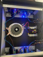
Below is a picture of an amp camp with torroidal and 2 CapMX boards.
One thing I realized I need to do is add a glb to my Amp camp I built with torroidal PSU. I need to add a CL-60 to each 0V connection in the amp.
Below is a picture of an amp camp with torroidal and 2 CapMX boards.
Attachments
For the ACP you won't really need the CL-60s for inrush current limiting as the caps in your picture don't look too significant which would result in a ton of inrush current that needs limiting. Here however, is where you might benefit from lifting the ground with the Glassware board I mentioned earlier. Before you go there, you can check to see if this cures your additional noise you are hearing by putting a CL-60 or fairly low value resistor between where you connect the negative/return paths to the chassis's earth ground on the IEC plug. The idea is to provide "a little" resistance that must be overcome to use the Earth path, which is what you want otherwise it can form a secondary return path (i.e.: ground loop). You can also measure this with a DVM/scope which you can find in the various threads in the Pass forums, or ping me offline if you need help with that.Quick update, I was able to confirm continuity in the ACP chassis and the hum is lower than it was before but it’s still there. Since the speakers are horn loaded I can barely hear the hum unless I am 1 inch from the woofer, but when I step away the hum comint out the back horn opening is slightly noticeable from center position a couple feet away.
One thing I realized I need to do is add a glb to my Amp camp I built with torroidal PSU. I need to add a CL-60 to each 0V connection in the amp.
Below is a picture of an amp camp with torroidal and 2 CapMX boards.
Take a look at 6L6's build guide for how to hook up the CL-60s: https://www.diyaudio.com/community/threads/a-guide-to-building-the-pass-f4-amplifier.234355/Yes. The CL-60 would be for the Amp camp amplifier.
I did build one of these yesterday I can try to implement into the camp camp and see if it works
Looks perf, and is effective. I use the same solution, from the F5 Turbo manual. Easier to connect too.Yes. The CL-60 would be for the Amp camp amplifier.
I did build one of these yesterday I can try to implement into the camp camp and see if it works
is there no hum when only the ACA is connected to speakers, with shorted inputs?
With inputs shorted there is still the very low level hum.
I did try a ground loop breaker in between chassis ground but it did not work. I am now wondering if my issue is more the amp and not the preamps.
I did try a ground loop breaker in between chassis ground but it did not work. I am now wondering if my issue is more the amp and not the preamps.
Hello Dneu2011,
your groundloopbreaker is not connected correctly.
One wire of the GLB goes to the Earthground, the other wire to the audioground of your amp.
In single- ended designs the GLB is often not so helpful. My experience is, that it has bigger benefits in
complementary amps (N- / P- channel) with symmetrical PSUs.
Cheers
Dirk
Please confirm that you have discovered the hum is still there with the preamps disconnected from the poweramp.With inputs shorted there is still the very low level hum.
I did try a ground loop breaker in between chassis ground but it did not work. I am now wondering if my issue is more the amp and not the preamps.
then tell us if there is hum with both inputs of the poweramp shorted, and whether it changes with the inputs open (not shorted).
it will then be easier to help you along, knowing if the problem is the preamp(s) or the ACA. My guess is the ACA
Dirks remarks are very good. I brainfarted wrt the glb. In your PSU, I am in fact a bit unsure how it actually connects 🙂
regards,
Andy
- Home
- Amplifiers
- Pass Labs
- Amp Camp Pre+Headphone Amp - ACP+