Hi Mooly
thanks for your help. i rechecked but i guess i did an error on the scope display resolution. i always have the Rigol1054 at Normal...but here i get all scoped points. i use a differential probe.
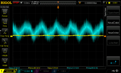
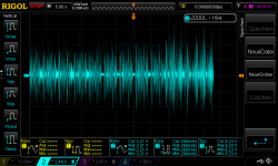
if i use peak detect or hi res mode then all look "normal". the load current is about 1,23A
i tried to change the voltage to get less output load current and under 0.5A i got nearly 10mVpp ripple.
pic 1 is at the input of the regulator pcb....with my lab supply
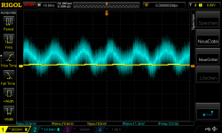
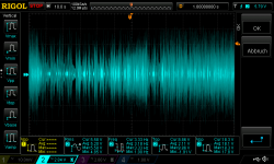
pic 2 is output voltage at the load resistors
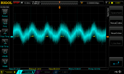
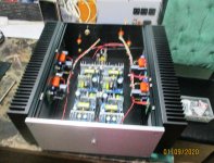
pic 3 is with the ACA supply set of 20,5V - thats the input of the regulator and then i got 18,4 at the output of the regulator
chris
thanks for your help. i rechecked but i guess i did an error on the scope display resolution. i always have the Rigol1054 at Normal...but here i get all scoped points. i use a differential probe.
if i use peak detect or hi res mode then all look "normal". the load current is about 1,23A
i tried to change the voltage to get less output load current and under 0.5A i got nearly 10mVpp ripple.
pic 1 is at the input of the regulator pcb....with my lab supply
pic 2 is output voltage at the load resistors
pic 3 is with the ACA supply set of 20,5V - thats the input of the regulator and then i got 18,4 at the output of the regulator
chris
Attachments
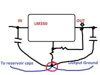
You have to use the correct ground point for the measurements.
The regulator chip uses this marked point as a ground reference. Nowhere else. If you connect the scope ground to say the reservoir cap then you will not get a true reading of the output voltage. That point is wired back to the reservoir cap and the output ground lead is also wired from this point.
With the chip connected as shown and the scope ground connected to this point you see a clean trace if you then probe this same ground point. Its a good test of your set up.
Any noise you then see (on that ground spot) is purely the result of the test set up and will be present in other measurements you take.
Attachments
Hi Mooly
THX.
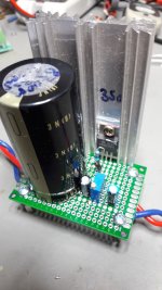
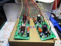
jop...you are right i just make a short cable as "ground" from the output to the small cap at the output and not to that referenz GND point.. have a look at my quick and dirty board
at the bottom side you see the GND line at the top of the pic, the blue cable on the right is output. at the left sid you sse the 10µF and 220nF parallel to the 10mF old DENON cap.
chris
THX.
jop...you are right i just make a short cable as "ground" from the output to the small cap at the output and not to that referenz GND point.. have a look at my quick and dirty board
at the bottom side you see the GND line at the top of the pic, the blue cable on the right is output. at the left sid you sse the 10µF and 220nF parallel to the 10mF old DENON cap.
chris
Attachments

Last edited:
That's not so bad 🙂
So for testing you need to ensure that there are no ground loops formed by the test equipment. Use the blue output ground wire as the ground test point.
Have you done the test of seeing if the scope gives a clean trace when probing 'ground'.
So for testing you need to ensure that there are no ground loops formed by the test equipment. Use the blue output ground wire as the ground test point.
Have you done the test of seeing if the scope gives a clean trace when probing 'ground'.
Good Morning Mooly😉
I will re check all what you have posted the last 3-4 times and then i report back.
chris
I will re check all what you have posted the last 3-4 times and then i report back.
chris
Good evening,
yesterday i listening to ACA and enjoy the sound. compared to my other amps it is a very relaxed and closed and flow interpretation. i miss a bit of more"energy" at the high and with the separation of vocals and instruments i expect a bit better.
my C1 (output cap) configuration is missing a foil cap?
my C1 is a 5600µF 16V Rubicon YXH + 100µF 16V Elna Silmic 2 and a nichicon FW 47µF 25V
what I like is the flow/timing and the bass. it is very deep and it is punchy enough for my taste...maybe at some titles a bit too bloated but I have just connect the SMPS without having a supply cap at the pcb.
no temperature problems - i can hold my hand more then 15seconds on the top of the amp...no problem. the bias with 1,57A is still the advantage and the limit for this housing @ 20,30V supply
When i switch to the ACA it is immediately a very "live" feeling. in respect of some Watt into my 4R speakers it is amazing what this amp can do.
Thank you Mr. Nelson PASS to made this possible for us DiY😉
chris
PS: yes i am hungry to try some SQ mods...
Last edited:
That's not so bad 🙂
So for testing you need to ensure that there are no ground loops formed by the test equipment. Use the blue output ground wire as the ground test point.
Have you done the test of seeing if the scope gives a clean trace when probing 'ground'.
Hi Mooly
Back to technical work......
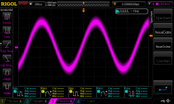
pic 1
i tested the differential probe directly at the output of my frequency generator and its looks very noise...
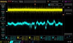
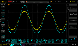
pic 2
its done by normal probes input (yellow) from my lab supply...noise switcher ... and blue is the output of the red cable directly at the load resistor. resistor is 3x 8,2R and with 20V i got about 0,81Amps. as GND i use the recommended point as you wrote. in the graph you can see with the resolution of 500msec per Div that the reg is doing its job....no really noise....
the failure was an electrical contact from the heat sink to the upper side of the pcb and because some solder dots are a bit with solder i got a short .....sometimes🙄
chris
Attachments

Good Morning Mooly😉
I will re check all what you have posted the last 3-4 times and then i report back.
chris
Hi Mooly
Back to technical work......
pic 1
Well that's looking a bit better 🙂 that 50Hz component has gone now

...can i go up with the voltage?...
During some listening test i ask myself:
Q1 can i go up with the Voltage to get more power or not?
Q2 what is the power level what i am listening with my new speakers (NADA 4R)
1
clarification of the temperature:
after running the amp without signal about 1,5hours i got at 2x IRFP240 about 70°C - the overall heat sink of my amp is fine because i can hold my hand 1minute on the heat sink without problems. voltage is 20,3V at the amp board and bias is 1,57A, --->AP is 10,3V
2
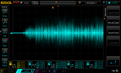
picture 1,2,3 show you some listening examples scoped with a long time setting to get and overview how loud is my listening level at different music styles.
with AP 10,3V and supply of 20,3 o got theoretically 10Vpeak as max.
pic 1 namika_live_ alles was zählt_3,1Wrms_10.7Watt peak_4R
pic 2 joe_sample_black and white_2,57Wrms_16,9Watt peak_4R
pic 3 adam_ben_ezra_downtown blues_7,78Wrms_19,6Watt peak_4R
so am in the rating of the amp and with my power setup i am at 70°C.
supply 24V? its about 6Watt more!!
what happened if i get a IRFP240 more then 70--> 80° is the chip noisy or brake down at some time because of internal material...??
chris
During some listening test i ask myself:
Q1 can i go up with the Voltage to get more power or not?
Q2 what is the power level what i am listening with my new speakers (NADA 4R)
1
clarification of the temperature:
after running the amp without signal about 1,5hours i got at 2x IRFP240 about 70°C - the overall heat sink of my amp is fine because i can hold my hand 1minute on the heat sink without problems. voltage is 20,3V at the amp board and bias is 1,57A, --->AP is 10,3V
2
picture 1,2,3 show you some listening examples scoped with a long time setting to get and overview how loud is my listening level at different music styles.
with AP 10,3V and supply of 20,3 o got theoretically 10Vpeak as max.
pic 1 namika_live_ alles was zählt_3,1Wrms_10.7Watt peak_4R
pic 2 joe_sample_black and white_2,57Wrms_16,9Watt peak_4R
pic 3 adam_ben_ezra_downtown blues_7,78Wrms_19,6Watt peak_4R
so am in the rating of the amp and with my power setup i am at 70°C.
supply 24V? its about 6Watt more!!
what happened if i get a IRFP240 more then 70--> 80° is the chip noisy or brake down at some time because of internal material...??
chris
Attachments
I would suggest in the first instance that you give this a try. Lets put some numbers into what you really need:
A Test. How much Voltage (power) do your speakers need?
The required files are in post #2
A Test. How much Voltage (power) do your speakers need?
The required files are in post #2
Hi Chermann, just out of interest, the Nada speakers tell me something. But what does 4R mean?
I run my ACA in combination with a Whammy as a preamp on 4 ohm Quadral Shogun. That gives enough power for my speakers to get more than room volume.
I run my ACA in combination with a Whammy as a preamp on 4 ohm Quadral Shogun. That gives enough power for my speakers to get more than room volume.
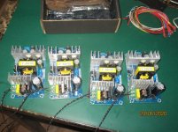
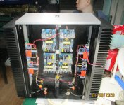
i made a 48v dc ACA amp, i used 4 x 48vdc smps bricks and 4 channels of 48V ACA.....power is a plenty for my 90db floor stander....
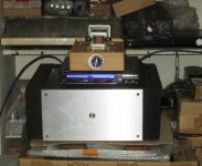
chassis from AliExpress and heatsinks by Conrad Engineering , MF 150 x 350
this is a bridged amp btw, you can bridge the 24v ACA too...
chassis from AliExpress and heatsinks by Conrad Engineering , MF 150 x 350
this is a bridged amp btw, you can bridge the 24v ACA too...
Attachments
Last edited:
4R = 4 ohm
different way of saying the same thing.
yep
the NADA DiY is a 4ohm impedance speaker...thats 4R😉
I would suggest in the first instance that you give this a try. Lets put some numbers into what you really need:
A Test. How much Voltage (power) do your speakers need?
The required files are in post #2
thanks mooly
i am not afraid to have to less watt...i am afraid about shorting the MOSFET because of overheat! that way i am a bit sissy😀 about the MOSFET temperature😀😀
i made a 48v dc ACA amp, i used 4 x 48vdc smps bricks and 4 channels of 48V ACA.....power is a plenty for my 90db floor stander....
chassis from AliExpress and heatsinks by Conrad Engineering , MF 150 x 350
this is a bridged amp btw, you can bridge the 24v ACA too...
WOW Tony😱
thats an ACA MONSTER🙂but i just see 2 pairs of speaker terminals ??
Last edited:
Hi
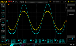
i played around with the setup of the bias point/voltage point.
first pic you can see my setup with i use the last days to enjoy the sound...😉😉
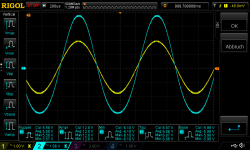
pic 2
then i decided to made the output symmetrical as i can. that means AP 8,73V. symmetrical as i can with 1320mVrms input i get on the top clipping.
Q1 56°C Q2 70°C
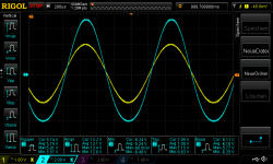
pic 3
AP at 11,96...max power with 1530mVrms input, very unsymmetrical. the lower part of the sine wave is "sticky" before the 3 line of V/Div. its not a nice sine wave..Q1 76°C Q2 65°C
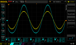
pic 4 AP at 11,23 nearly the same as AP11,96 but little less power. the bottom line is still "fixed" near the 3 line and the sine wave looks strange.
Q1 70°C Q2 67°C
to be honest i am not sure i can interpret my measurements correctly...means should i setup for much power and dont care about this soft clip lower part of the sine wave...or should i setup the AP to 8,73 to get a "cleaner" wave for and maybe better sound?😕😕😕
chris
i played around with the setup of the bias point/voltage point.
first pic you can see my setup with i use the last days to enjoy the sound...😉😉
pic 2
then i decided to made the output symmetrical as i can. that means AP 8,73V. symmetrical as i can with 1320mVrms input i get on the top clipping.
Q1 56°C Q2 70°C
pic 3
AP at 11,96...max power with 1530mVrms input, very unsymmetrical. the lower part of the sine wave is "sticky" before the 3 line of V/Div. its not a nice sine wave..Q1 76°C Q2 65°C
pic 4 AP at 11,23 nearly the same as AP11,96 but little less power. the bottom line is still "fixed" near the 3 line and the sine wave looks strange.
Q1 70°C Q2 67°C
to be honest i am not sure i can interpret my measurements correctly...means should i setup for much power and dont care about this soft clip lower part of the sine wave...or should i setup the AP to 8,73 to get a "cleaner" wave for and maybe better sound?😕😕😕
chris
Attachments
i made a 48v dc ACA amp, i used 4 x 48vdc smps bricks and 4 channels of 48V ACA.....power is a plenty for my 90db floor stander....
chassis from AliExpress and heatsinks by Conrad Engineering , MF 150 x 350
this is a bridged amp btw, you can bridge the 24v ACA too...
SWEET! Have you measured the actual wattage output? Curious to know how much you can get.
Hi
sorry my previous post is not really correct. because of the Voltage setup point i use the lower part of the resistors 2 x 0,68R where the drain of Q1 is and not the point before C1. so you have to add 0,53V (2x0R68// --> 0R34 and 1,57A = 0,53V)
additionally i measured now the left channel and this channel looks better and more symmetrical.
AP is pic 1 10,74 as i listening the last time
pic 2 is AP 12,08V
Q1 54°C Q2 63°C
so it looks like that i have at the R channel a symmetrical problem ? i did a short measurement again and it looks that the bottom part of the sine wave is very early "bloated" and the more i psuh the output i can see that the upper part is growing and gets bigger and bigger but the lower part of the sine wave is moving not really and gets more bloated.
whats that??
chris
Attachments

Last edited:
- Home
- Amplifiers
- Pass Labs
- Amp Camp Amp - ACA