Here are some measurements on your speaker: SoundStage! Measurements - B&W CM1 Loudspeakers (5/2007)
And another: CM1 Measurements and Analysis | Audioholics
It helps put your review in context.
That's quite the trough at 2k.😱
jeff
Indeed, I personally would believe the NRC measurements over the Audioholics measurements which do not show that trough.
But more importantly, the NRC shows you a "listening window" FR curve where you see on an overall sensitivity of 79-81dB @ 1m for this speaker. Since this was measured in an anechoic chamber there are no reflections. In a regular room you should get a few dB more. The impedance low is also 4 ohms at really one area (150-250 Hz), but everywhere else the impedance is higher. Phase angles are also benign as it should be with a 2 way. Bear in mind the output impedance of the ACA is > 2 ohms.
I'll be interested to see the UMIK-1 measurements and see how they compare, at least in > 300Hz area.
All a bit off topic, my apologies.
Best,
Anand.
Thanks, Anand. I looked at those once upon a time prior to buying the speakers, then re-created them in my listening environment with the Umik-1 and REW.Here are some measurements on your speaker: SoundStage! Measurements - B&W CM1 Loudspeakers (5/2007)
And another: CM1 Measurements and Analysis | Audioholics
It helps put your review in context.
Best,
Anand.
Nice system you have there!


The Boards have arrived....next weekend ACA should be playing music in my ears
Sent from my iPhone using Tapatalk Pro
But confusing Attila, can you please reconfirm the caps details, also not very clear from the pic
Sent from my iPhone using Tapatalk Pro
Sent from my iPhone using Tapatalk Pro
Hi All,
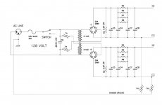
I'm working on the PSU for my "ACA on Steroids" and I need some advice. Planning on using the standard Pass PSU topology, except set up as dual mono single-voltage supplies rather than a pos/neg supply. I've attached a schematic of my proposed PSU. I'm planning on using the components I have on hand, so the caps will be 5600uf Elnas, and the pi resistors will be 1.2R. Bleeder resistors will be 2.2K. A couple of questions:
1) What is the value of C9? Am I correct in interpreting that as 330uf?
2) Is it imperative to use CL60 thermistors, or will CL50 (7R) or CL70 (16R) work? Don't know if my local electronics store has CL60, but they might have the others.
Thanks,
Chuck
Attachments
hi, @kpsthakur,
my acas only had the originally recommended 3300µF electrolytic cap (C1) but I always disliked the high frequency response. so after three years I thought it was time for a change.
The best electrolytic cap (I know of):>>http://de.rs-online.com/web/p/aluminium-elektrolytkondensatoren/1908911/<<
due to little space: one 10µF MKT:>>https://www.intertechnik.de/Shop/Frequenzweichenbauteile/Kondensatoren/MKT-axial-160-V/_MKTA10160_1768,de,7467,3876<<
and for smooth high frequency 0,47µF Tinfoil:>>https://www.intertechnik.de/Shop/Frequenzweichenbauteile/Kondensatoren/Audyn-Cap-KP-SN/_KPSN047250_1768,de,277,48479<<
all three in a parallel constellation acting as one cap.
the big sikorel cap had to be placed next to the pcb, wire connected, glued with silicone.
the acas are driven by my ba3fe clone and play exquisite with my 93dB Isophon Orchester 2000 from 1976 as well as less sensitive SMGA Magneplanars.
->amp pictures in the gallery
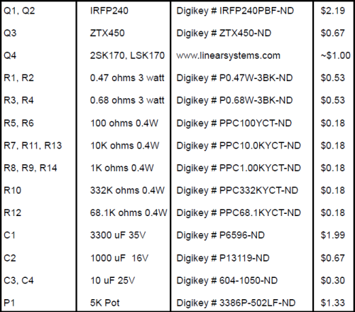
THe suggested trimmer resistor is 5K 0.5w in part list.
Can i use 5K 250mw (1/4w) resistor?
Thanks in advance.
Can i use 5K 250mw (1/4w) resistor?
Thanks in advance.
THe suggested trimmer resistor is 5K 0.5w in part list.
Can i use 5K 250mw (1/4w) resistor?
Thanks in advance.
If you're talking about a 1/4W 5K trimmer then I think it's ok. (Make sure footprint fits PCB.)
If you're talking about a 1/4W 5K fixed resistor then the answer is definitely no.
Troubleshooting no sound
I just built a pair of ACA's and I've got no sound coming from one, with 0V on Pin 2 of Q1. I've not had much luck (or enough patience?) with searching the forum for troubleshooting/testing steps. Any recommendations?
Thanks,
Jim
I just built a pair of ACA's and I've got no sound coming from one, with 0V on Pin 2 of Q1. I've not had much luck (or enough patience?) with searching the forum for troubleshooting/testing steps. Any recommendations?
Thanks,
Jim
recheck all solder joints , resistor values
put some pics here

I did have difficulty with getting good soldering joints (especially the speaker binding posts) so I am very afraid I have cooked some component. The LED does light up, but when I power it off I don't get a thump in the speaker like I do with the other one.
Jim
It's working now, I touched up a few soldering points - pin 2 on Q2 was very suspect.
Thanks,
Jim
Thanks,
Jim
good praxis for greenhorns is to use some old pcb , for practicing desoldering,soldering, repairing of traces etc.
at least I started like that , few hundredthousand years ago
coincidence : http://www.diyaudio.com/forums/cons...me-soldering-lessons-youtube.html#post2955631
at least I started like that , few hundredthousand years ago
coincidence : http://www.diyaudio.com/forums/cons...me-soldering-lessons-youtube.html#post2955631
Duck: Gold plated pads (ENIG) on a pcb are harder to solder than tin plated pads. I pre-apply a little rosin flux (I think paste is the easiest to use) on the pad right before soldering.
For speaker binding posts, you need a larger soldering iron with a wide chisel tip for extra mass. I also melt a glob of solder on the end of the soldering tip to get a little more mass before soldering to large items.
For speaker binding posts, you need a larger soldering iron with a wide chisel tip for extra mass. I also melt a glob of solder on the end of the soldering tip to get a little more mass before soldering to large items.
Please try to scratch clean the pins, pads before soldering to remove oxidised layer, heat the pads using solder for 3-4 seconds before applying solder, solder will flow properly to heated pads and scratched pins probably called heat reflow method
Sent from my iPhone using Tapatalk Pro
Sent from my iPhone using Tapatalk Pro
- Home
- Amplifiers
- Pass Labs
- Amp Camp Amp - ACA