83db is very low, I used to have Celestion SL6 speakers and they were only 82db/W
So two ACA's. You have the option of parallel mode to get twice the current capability (if they are an adverse load) or bridge mode to get twice the voltage swing but with no increase in current delivery ability.
So much depends on what your idea of 'how loud I want it' is 🙂
This should give you a good idea:
https://www.diyaudio.com/community/...h-voltage-power-do-your-speakers-need.204857/
Thanks, Mooly
I am planning to use them in my near field setup.
Yes, I am thinking of bridged mode, too.
I am planning to use them in my near field setup.
Yes, I am thinking of bridged mode, too.
certainly yes, if used as they're designed for - near field
if you have 16R version, think of bridged ACA, practically you need 2 stereo ACA to get there
edit: I see Mooly and you got it all in meantime
if you have 16R version, think of bridged ACA, practically you need 2 stereo ACA to get there
edit: I see Mooly and you got it all in meantime
Here is a short video of Amp Camp Amp playing on Sound Artist LS3/5a,

I was thinking about it last night but is it possible to use the input stage (in other words, a single SK170 as a buffer) of the ACA before a volume pot albeit with alterations to buffer before a volume pot?
This is a consideration for me as I'm converting into a headphone amp and may need to dial the volume down if my DAC doesn't go low enough or in the case of annoying direct DSD files that go full tilt
(mostly because I don't wish to add a B1 in front of it just for the purpose of a volume pot buffer)
Do I include P1 and R10 to set up a DC voltage on the gate of the buffer as well? I can do a basic electronics way of JFET buffer but I wanna hear the pro opinions on adding a simple buffer based on a single jfet
Not a pro, but you could do the B1 Korg version of the input buffer. Either SK170 or J113 for the follower JFET and a J113 for the CCS. And use the ACA power supply for power.
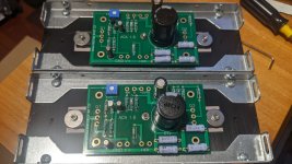
I am an evangelist for using Kapton tape and heatsink compound instead of any other stuff ...also using an alu bar/channel (with a coating of heatsink compound) to press down the device to the heatsink always obtains better heat transfer, IMO.the ones which come with transistors,
View attachment 1185527
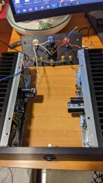
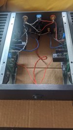
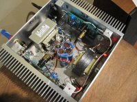
Good build Amrut, though you must tidy up the wiring ...
👍
B1K board into ACA amp. I've seen posts where people have talked about one driving the other, but has anyone physically installed the B1K into an existing ACA 1.8 stereo amp case to create an integrated amp. The 24V already exists, just need to drill a hole for the volume pot, and do a bit of rewiring. Apologies if somebody has but I've not seen the post (I did a search).
I have the ACA 1.3 mono blocks. My original 19V power supplies developed an audible hum, so I stopped using them. I could get the 24V meanwells from the store or I could build linear power supplies for them. Would 200VA 2x18V transformers work for each channel? How much capacitance is needed per channel?
i am working on wiring the back panel, but where do i get this braided wire on step 8 of 1.8 wiring:
https://d3t0tbmlie281e.cloudfront.net/igi/diyaudio/NgFuaPk12ljlAbKN.huge
i didnt see this in my wiring packet, am i supposed to strip a bunch of the colored wires to make this?
edit:sorry i found it, needed to strip the black wire
https://d3t0tbmlie281e.cloudfront.net/igi/diyaudio/NgFuaPk12ljlAbKN.huge
i didnt see this in my wiring packet, am i supposed to strip a bunch of the colored wires to make this?
edit:sorry i found it, needed to strip the black wire
Last edited:
sorry i couldn't edit my last post
Can i adjust the DC balance of the ACA without any speakers connected? I read amplifiers cant be turned on without a load when i used to read about guitar amplifiers. is that only for tube amplifiers?
Can i adjust the DC balance of the ACA without any speakers connected? I read amplifiers cant be turned on without a load when i used to read about guitar amplifiers. is that only for tube amplifiers?
You can adjust without a load. Also make sure you have no signal applied.
General rule is that solid state amps are normally fine with no load (and I can't think of any that are not) while valve amps with an transformer output stage should always have a load, and especially so if there is any signal present. This is because you can get very high interwinding voltages caused by uncontrolled oscillation if unloaded that can cause breakdown of the insulation of the windings.
General rule is that solid state amps are normally fine with no load (and I can't think of any that are not) while valve amps with an transformer output stage should always have a load, and especially so if there is any signal present. This is because you can get very high interwinding voltages caused by uncontrolled oscillation if unloaded that can cause breakdown of the insulation of the windings.
i finished my build for ACA 1.8 today. I was so surprised that it worked right away. I would of assumed there would be a goof some where and i needed to use that troubleshooting guide and get some troubleshooting experience.
so surprised to see how hot the chassis gets(i measured 108-114F) in the heatsink fins
my remaining problems is getting used to the sound levels and the missing sub woofer and not having working RCA cables after getting it connected to my PC. i found some old RCA cables and they are all scratchy and cut out and they need to be reseated or adjusted to get back to working order. I ordered a new RCA cable from Amazon but forgot to buy a 2nd one. ill make due with 1 new and 1 old RCA cable until the new one arrives.
the build guide was very helpful with all the pictures, but there are multiple moments where reading ahead is very much needed and a bit of planning. there were some moments where a novice like me (or someone dumb like me lol) didnt even know where the braided wire would be as ingesting all the instructions was not done(i thought i read as much as i could before the build 🙁 ). I have left over screws and washers and some of the hardware no longer matched the build guides. I made it to the end and i have a amplifier!
now i have tools for soldering, but i dont know what i can build next (looking for some low cost projects or something that i can use after i build).
thank you diyaudio for a fun build! thank you to forum members for answering my questions on both the ACA build and tools
Attachments
I have a power supply question.
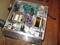
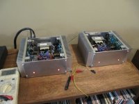
First a bit of background. I've built 5 of these so far. (I can't help buying in bulk, so my last batch I bought enough for 2 stereo amps and 2 bridged mono blocks.) My son and daughter are both enjoying ACA stereo amps. My post is about 2 bridged monoblocks I just built. I have one in the parts bin, and the UPS driver (I assume) is enjoying the first stereo amp I shipped to my daughter.
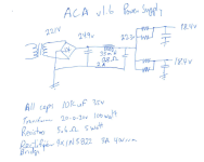
I've used Meanwell power supplies, but thought I'd give a linear ps a try for the bridged mono blocks. It is a pi filter with a choke - CLCRC. (See attached.) I expected the design to give me just under 24v. But I am getting 18.4v. (I set the drains to 10v.)
I was under the impression that each channel (board) draws 1A, but from what my PS is telling me it is more like 1.5A.
I think my rectifier bridge diodes are underspec'd (IN5822 3A 40vrrm) and my dc volts after the bridge rectifier is way under my expectation.
Also, I figure the 2A rated choke is saturated.
But even with all this, the ps seems to be supplying nice clean dc. Amps are dead quiet. I think the CLC is promising.
And yes, the sound is pretty amazing.
So, any consensus on the 1.5A draw per board? Is this expected?
And my bridge rectifier getting 22VAC and outputting 24.9vdc means my rectifier diodes are under spec'd, right. I was expecting 28vdc with 20VAC secondaries (but with the 100 watt transformer the secondaries are at 22.1VAC.
First a bit of background. I've built 5 of these so far. (I can't help buying in bulk, so my last batch I bought enough for 2 stereo amps and 2 bridged mono blocks.) My son and daughter are both enjoying ACA stereo amps. My post is about 2 bridged monoblocks I just built. I have one in the parts bin, and the UPS driver (I assume) is enjoying the first stereo amp I shipped to my daughter.
I've used Meanwell power supplies, but thought I'd give a linear ps a try for the bridged mono blocks. It is a pi filter with a choke - CLCRC. (See attached.) I expected the design to give me just under 24v. But I am getting 18.4v. (I set the drains to 10v.)
I was under the impression that each channel (board) draws 1A, but from what my PS is telling me it is more like 1.5A.
I think my rectifier bridge diodes are underspec'd (IN5822 3A 40vrrm) and my dc volts after the bridge rectifier is way under my expectation.
Also, I figure the 2A rated choke is saturated.
But even with all this, the ps seems to be supplying nice clean dc. Amps are dead quiet. I think the CLC is promising.
And yes, the sound is pretty amazing.
So, any consensus on the 1.5A draw per board? Is this expected?
And my bridge rectifier getting 22VAC and outputting 24.9vdc means my rectifier diodes are under spec'd, right. I was expecting 28vdc with 20VAC secondaries (but with the 100 watt transformer the secondaries are at 22.1VAC.
Attachments
1.5A sounds right where it should be tbh. When the voltage across R15 reaches around 0.6 volts then Q3 comes into conduction holding the current constant. So you can work out the volt drop needed across the 0.47 and .68 ohm resistors to get that value and around 1.5A (or a little more) is spot on.
I snipped the power to one board to see what happens with just one channel powered.
The voltages changed as follows (before/after):
Transformer secondaries - 22.1VAC/22.2VAC
After bridge rectifier - 24.9v/26.5v. I expected 30.4v with that secondary voltage.
After choke @1.0ohm - 22.3v/25.1v
B+, last resistor 2.9ohm - 18.4v/21v
So the voltage drop across the choke and resistor calculate to 1.4A. The drains are set at 10v, so maybe 1.4A is in the ballpark.
Why would the rectifier bridge not put out 30.4v ((22.2VAC x 1.4) - 0.6)? What am I missing?
I think I will move this over to the power supply forum. Thanks.
- Home
- Amplifiers
- Pass Labs
- Amp Camp Amp - ACA