Right! I've got an 8 ohm dummy load across speaker terminals (A-,B-). Scope probe attached at output A- and probe ground attached to B-. Wave form clips at about 2.5V input and about 8V output. That equates to about 8 watts.
Shouldn't I be able to push the output voltage to something like 11V?
Am I missing something here?
Make sure the scope ground lead is not applying a short to one channel. The scope normally needs to float to measure like this.
I'm sure I did short out one channel...thankfully nothing was damaged. I tested the channels in stereo mode again and everything is fine. I connected them (ACA in parallel mode) in my system and they sound wonderful!
I knew that I was missing something...turns out it's an understanding of how the bridged output of an amplifier works.
I've been doing some reading about the nature of amplifiers with bridged output and how to measure them. i tried summing the oscilloscope channels (with probes floating this time) using the math function while having one channel inverted with mixed results.
If I really want to pursue measurements of amplifiers with bridged output then a differential scope probe would be in my future.
I'm sure I did short out one channel...thankfully nothing was damaged. I tested the channels in stereo mode again and everything is fine. I connected them (ACA in parallel mode) in my system and they sound wonderful!.
That's good, and there are zero worries over damaging the ACA by doing that, it won't mind at all. Its a Class A thing.
The overall current draw is set by the current source Q2 and Q3 and the lower the load impedance and the more of that current in the output FET's is diverted to the load. It should actually run cooler believe it or not. Worst case is actually idling with no load and/or no signal.
So all good.
We'll get there 🙂
With the amp OFF and a speaker connected can you hear any thump or noise from the speaker as you turn the amp on and then off?
Have you done all the continuity tests I detailed? that will test and check for both continuity and also inadvertent shorts.
Amp Camp Amp - ACA
Hey guys. Sorry for the slow response. Only get a limited time each week. I will look at this tomorrow and let you know how I get on.
😎
We'll get there 🙂
With the amp OFF and a speaker connected can you hear any thump or noise from the speaker as you turn the amp on and then off?
Have you done all the continuity tests I detailed? that will test and check for both continuity and also inadvertent shorts.
Amp Camp Amp - ACA
OK. So, it sounds pretty much the same as my working amp. The funny farty noise that we all know and love. Along with a gentle thud when switching off.
I need to look at the continuity list and work through it. I might have pick your brains for each step though, as I don’t know what I’m doing 😆
Alex, you are getting some great advice here but can you work through this list and see where it falls down 🙂
You have to begin with the most basic tests and that begins with supply voltage and the DC conditions. I just can't spot anywhere where you have done that.
1/ The supply voltage of 24 volts has to be correct entering the board (or as measured on the middle lead of Q2). Be extremely careful not to short to the other leads when checking.
2/ The FET's and the heatsink should be hot after a few minutes. The voltage measured across any one of the 0.47 ohm resistors should be about 0.37 volts. The voltage across either 0.68 ohm should be about 0.55 volts.
3/ The voltage on the plus end of C1 (the big 3300uF speaker coupling cap) should be about 12 volts and be adjustable with the preset.
4/ The positive speaker socket should read zero (0.00) ohms to ground.
5/ The negative speaker socket should read zero (0.00) ohms to the negative end of C1.
6/ The outer part of the RCA socket should read zero (0.00) ohms to ground.
7/ The inner connection of the RCA socket should read zero (0.00) ohms to one side of R11.
8/ There should be no short between inner and outer of the RCA. You should see higher than 10k here.
9/ There should be no short between the positive and negative speaker sockets.
Note.
0.00 ohms is a short but your meter will probably show something a little higher due to lead resistance, for example 0.2 ohms if you short the probes together on the low ohms range.
All these tests also assume that 'ground' is OK and that the 0 volt line of the power supply is connected correctly. The common point on the PCB that R14, R9 and the Source of Q1 connect to is 'Ground' for measurement purposes.
So, 1,2 & 3 are checked and all good. So on to 4. How do I do this?
First set your meter on a low ohms range and as a meter test short the probes together and check you read almost zero ohms. A reading of 00.1 or 00.2 ohm is the resistance of the meter leads.
Now connect the black lead to the speaker plus socket and the red lead to any ground point on the amp such as outer part of the RCA sockets or any ground point on the PCB and check you read similar to when the probes were shorted.
Note... the fact you hear the same noises as the working amp is going to tell us that the speaker continuity (4 and 5 above) is OK but it is good practice for you to check it.
Hello!
I just finished building a pair of ACA amps. It took 3 days because I've never done a ground up build before and I didn't want to screw it up. Oddly nothing blew up when I turned them on for the first time yesterday and they measure correctly as well as virtually identically in each of the (3) modes of operation. Amazing.
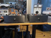
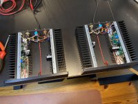
My initial application will be the high frequency section of a pair of biamplified Klipschorns with 8Ω B&C DE750 drivers on Dave Harris Tractrix horns covering 450Hz-16kHz or so. Their 108dB 1 watt sensitivity indicates that the little ACA amps should provide plenty of SPL. I'll be using a larger amp for the low frequency sections.
The thing that caught my interest in these amps was Nelson Pass and his particular take on high-end amplification that I've yet to experience. The low cost of the amp kits sealed it.
I'm a measurement nut. I haven't even listened to the amps yet and wanted to be dead sure they worked properly first - because I don't trust the guy that built them. I also wanted to see what Papa Pass's amplification philosophy looked like through analyzers that I've been using in audio for decades, professionally and as a hobbyist.
The ACA amp is fascinating. It is the definition of a minimalist design and how it handles overload is the most graceful thing I've ever measured. Tomorrow I will have my first chance to listen to the amps and my expectation is that I won't notice the distortion until it's 5 or 10 times higher than any other amp I have. I restored a pair of MC275's a while ago and they have a subjectively soft overload quality. My measurements today indicate that the little ACA amps are better still in this regard by a large margin. We'll see.
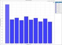
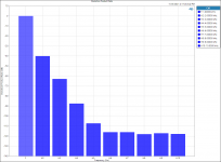
Compare the 1kHz 1% THD harmonic output of the MC275 into 4Ω with the ACA amp at the same frequency, THD level and load. Both amps in stereo mode, both channels driven.
MC275
ACA Amp
Now compare the scope output of these two amps at 1kHz and 3% THD (the higher THD level accentuates the differences). The smaller waveform is the distortion component raised 20dB (10x).
MC275
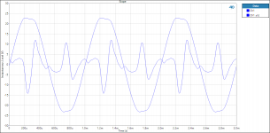
ACA Amp
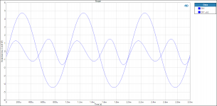
More to come.
God bless you and your precious family - Langston
I just finished building a pair of ACA amps. It took 3 days because I've never done a ground up build before and I didn't want to screw it up. Oddly nothing blew up when I turned them on for the first time yesterday and they measure correctly as well as virtually identically in each of the (3) modes of operation. Amazing.


My initial application will be the high frequency section of a pair of biamplified Klipschorns with 8Ω B&C DE750 drivers on Dave Harris Tractrix horns covering 450Hz-16kHz or so. Their 108dB 1 watt sensitivity indicates that the little ACA amps should provide plenty of SPL. I'll be using a larger amp for the low frequency sections.
The thing that caught my interest in these amps was Nelson Pass and his particular take on high-end amplification that I've yet to experience. The low cost of the amp kits sealed it.
I'm a measurement nut. I haven't even listened to the amps yet and wanted to be dead sure they worked properly first - because I don't trust the guy that built them. I also wanted to see what Papa Pass's amplification philosophy looked like through analyzers that I've been using in audio for decades, professionally and as a hobbyist.
The ACA amp is fascinating. It is the definition of a minimalist design and how it handles overload is the most graceful thing I've ever measured. Tomorrow I will have my first chance to listen to the amps and my expectation is that I won't notice the distortion until it's 5 or 10 times higher than any other amp I have. I restored a pair of MC275's a while ago and they have a subjectively soft overload quality. My measurements today indicate that the little ACA amps are better still in this regard by a large margin. We'll see.
Compare the 1kHz 1% THD harmonic output of the MC275 into 4Ω with the ACA amp at the same frequency, THD level and load. Both amps in stereo mode, both channels driven.
MC275

ACA Amp

Now compare the scope output of these two amps at 1kHz and 3% THD (the higher THD level accentuates the differences). The smaller waveform is the distortion component raised 20dB (10x).
MC275

ACA Amp

More to come.
God bless you and your precious family - Langston
Last edited:
Nope. Still haven't listened to them. Tonight. 🙂
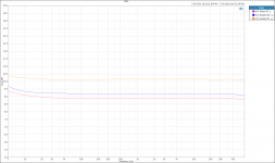
The gain of these ACA amps is about 9dB Stereo or Bridged and about 10dB in Parallel mode. The circuit gains are about the same across modes, thus the additional gain in Parallel mode is due to the halved output impedance (relative to Stereo mode). By this reasoning, you'd expect Bridged mode to have the least gain because of its doubled output impedance (relative to Stereo mode), but I used an 8Ω load resistor in that case, thus the slightly higher gain than Stereo mode. I prefer very low amp gains like this because it improves the gain structure (S/N) of the system assuming your preamp can provide the voltage needed to drive the amp to its max. output. The Benchmark ACB2 amp is probably the S/N champ and it has a 9.2dB gain option to achieve this. Papa Pass hit several useful birds at once with the low gain stone.
Stereo, Bridged and Parallel mode gains measured into 4Ω, 8Ω and 4Ω respectively
Going further with the gain concept and the ACA Amp / MC275 comparison, I set both amps in Stereo mode with their left channels loaded by a 4Ω resistor and their right channels loaded by a nominal 4Ω 2-way moving coil loudspeaker simulation circuit.
Impedance of the LDSPK simulator
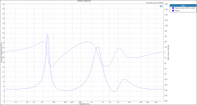
While damping factor is a red herring, the output impedance used to calculate it is not. The reason it's important is that it forms a voltage divider with the load, and when that load's impedance is variable, as it is with loudspeakers, it causes a variable frequency response - effectively a form of EQ. The lower an amp's output impedance, the less the effect, although... if the "EQ" sounds better, who am I to say it's "wrong"? 🙂 IMO, this effect is a primary reason some people prefer tube amps over solid state and vice-versa. The ACA amp has tube amp-like output impedance, thus will undoubtedly prove the best of both worlds for some and the worst for others.
You'll notice a bit more "EQ" variation with the ACA amp vs. the MC275, indicating the MC275 has a little lower output impedance across its 4Ω output terminals than the ACA amp in stereo mode. Not shown is the fact that the ACA amp in Parallel mode has lower output impedance than the MC275, thus less magnitude variation.
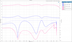
Magnitude and THD at -10dBV drive levels into 4Ω (light, dashed traces) and into the loudspeaker simulator (heavy, solid traces)
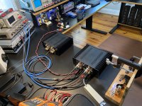
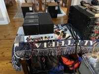
Measurement Setups
More to come.
God bless you and your precious family - Langston
The gain of these ACA amps is about 9dB Stereo or Bridged and about 10dB in Parallel mode. The circuit gains are about the same across modes, thus the additional gain in Parallel mode is due to the halved output impedance (relative to Stereo mode). By this reasoning, you'd expect Bridged mode to have the least gain because of its doubled output impedance (relative to Stereo mode), but I used an 8Ω load resistor in that case, thus the slightly higher gain than Stereo mode. I prefer very low amp gains like this because it improves the gain structure (S/N) of the system assuming your preamp can provide the voltage needed to drive the amp to its max. output. The Benchmark ACB2 amp is probably the S/N champ and it has a 9.2dB gain option to achieve this. Papa Pass hit several useful birds at once with the low gain stone.
Stereo, Bridged and Parallel mode gains measured into 4Ω, 8Ω and 4Ω respectively

Going further with the gain concept and the ACA Amp / MC275 comparison, I set both amps in Stereo mode with their left channels loaded by a 4Ω resistor and their right channels loaded by a nominal 4Ω 2-way moving coil loudspeaker simulation circuit.
Impedance of the LDSPK simulator

While damping factor is a red herring, the output impedance used to calculate it is not. The reason it's important is that it forms a voltage divider with the load, and when that load's impedance is variable, as it is with loudspeakers, it causes a variable frequency response - effectively a form of EQ. The lower an amp's output impedance, the less the effect, although... if the "EQ" sounds better, who am I to say it's "wrong"? 🙂 IMO, this effect is a primary reason some people prefer tube amps over solid state and vice-versa. The ACA amp has tube amp-like output impedance, thus will undoubtedly prove the best of both worlds for some and the worst for others.
You'll notice a bit more "EQ" variation with the ACA amp vs. the MC275, indicating the MC275 has a little lower output impedance across its 4Ω output terminals than the ACA amp in stereo mode. Not shown is the fact that the ACA amp in Parallel mode has lower output impedance than the MC275, thus less magnitude variation.
Magnitude and THD at -10dBV drive levels into 4Ω (light, dashed traces) and into the loudspeaker simulator (heavy, solid traces)

Measurement Setups


More to come.
God bless you and your precious family - Langston
Last edited:
Very cool, I am using my now modified amps with an Adcom GFP-750 Preamplifier which has 8.33db of gain unbalanced and 14.33db of gain balanced and it works really well either using one amp in stereo or balanced mono's!! I guess it keeps things Pass designed and Class A
First set your meter on a low ohms range and as a meter test short the probes together and check you read almost zero ohms. A reading of 00.1 or 00.2 ohm is the resistance of the meter leads.
Now connect the black lead to the speaker plus socket and the red lead to any ground point on the amp such as outer part of the RCA sockets or any ground point on the PCB and check you read similar to when the probes were shorted.
Note... the fact you hear the same noises as the working amp is going to tell us that the speaker continuity (4 and 5 above) is OK but it is good practice for you to check it.
Hello Mooly. I’ve performed the steps you suggested.
Lead resistance is 0.4ohms
Step 4: 0.5ohms
Step 5: starts around 1.5 but quickly ramps up to 3.2ohms
Step 6: 0.5ohms
Step 7: 0.5 on one side of resistor. No reading (1) on the other side
Looks like step 5 is the problem?
#5 isn't correct, it should be a direct wire connection and so be essentially zero ohms.
This 0.5 ohms you keep registering suggests that is what your meter intrinsically shows when measuring across what should be a short or zero ohm connection. Its not a problem in itself as long as you know the error exists.
S0 #5 should be absolutely rock steady and show 0.5 based on how your meter responds.
First thought is to check the cap is the correct way around.
As mentioned before... you hear the switch on thump etc and so the speaker must have continuity to the amp.
Lets work through it all though and see why you read that varying figure. If you look at the circuit you will see that it should be a direct connection so trace it through and find why your meter shows it have significant and varying resistance.
(Make sure your meter probes are clean. Any contamination will add to the reading)
Sorry just to clarify. The thump when I switch off is only happening in the working channel A. Not the channel in question.
Right! So, here goes …
I HAD THE OUTPUTS WIRED THE WRONG WAY
There. I said it lol.
It’s working in stereo now. I’m not sure what’s worse..getting them the wrong way round or having to come on here and say it! 😀
I HAD THE OUTPUTS WIRED THE WRONG WAY
There. I said it lol.
It’s working in stereo now. I’m not sure what’s worse..getting them the wrong way round or having to come on here and say it! 😀
Humility is really important because it keeps you fresh and new. -Steven Tyler
Also:
Said you ain't seen, nothin'
Til you're down on the muffin
And there's sure to be a change in ways - Steven Tyler
- Home
- Amplifiers
- Pass Labs
- Amp Camp Amp - ACA
 so we got there in the end