It will not. You have omitted the switch' other (available) contact, and wired the ACA outputs permanently for the parallel mode of operation.
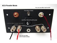
Parallel:
- inputs are paralleled by means of the little XLR connector that I plugged at the back
- outputs (negatives) are paralleled by means of the switch shorting the middle pins (one ACA module output), and the top pins (the other ACA module output).
Output can be taken of any (all) posts
Bridged:
- the switch will have to short the middle pins and the bottom pins (by doing this, it will also disconnect the outputs' parallel connection)
- you can wire the speakers now between two negative posts (two outputs).
Last edited:
Parallel:
- inputs are paralleled by means of the little XLR connector that I plugged at the back
- outputs (negatives) are paralleled by means of the switch shorting the middle pins (one ACA module output), and the top pins (the other ACA module output).
Output can be taken of any (all) posts
Bridged:
- the switch will have to short the middle pins and the bottom pins (by doing this, it will also disconnect the outputs' parallel connection)
- you can wire the speakers now between two negative posts (two outputs).
is this correct? im new to diy.
thanks for the help anyway.
Attachments
is this correct? im new to diy.
thanks for the help anyway.
The lines you added on the computer are a bit confusing. Can you show the photo without the extra lines?
is this correct? im new to diy.
thanks for the help anyway.
sure, no problem🙂
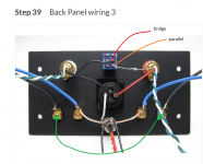
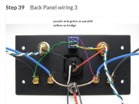
parallel: the purple wire should go from the top switch contacts to the other negative. the RCA middle pins should be shorted as well.
bridged: yellow wire not required
sure, no problem🙂
parallel: the purple wire should go from the top switch contacts to the other negative. the RCA middle pins should be shorted as well.
bridged: yellow wire not required
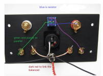
everything is follow the step 39 except this, am i right?
the yellow(blue in the photo) should be the resistor,
what do u mean by shorted rca?
in this case, is it balance cable no longer needed as the + - already link together (dark red)
Attachments
lifefordota
If you replace the original switch with a good quality DPDT On-Off-On type you can have all 3 modes. (Double Pole Double Throw with central Off position.)
See the picture.
So Switch Up = Bridged via White RCA.
Switch Central (Off) = Normal Stereo or XLR Bridged.
Switch down = Parallel Bridged mode.
Just Make Sure you do not move the switch with power on...
Alan
Attachments

Last edited:
lifefordota
If you replace the original switch with a good quality DPDT On-Off-On type you can have all 3 modes. (Double Pole Double Throw with central Off position.)
See the picture.
So Switch Up = Bridged via White RCA.
Switch Central (Off) = Normal Stereo or XLR Bridged.
Switch down = Parallel Bridged mode.
Just Make Sure you do not move the switch with power on...
Alan
i see, what if i maintain the original switch and without using stereo?
like, switch up bridge and switch down parallel. but xlr will not be functioning (as the + - is linked). is it like that?
im totally new thats why i hope that i can maintain with all the original parts.
i see, what if i maintain the original switch and without using stereo?
like, switch up bridge and switch down parallel. but xlr will not be functioning (as the + - is linked). is it like that?
im totally new thats why i hope that i can maintain with all the original parts.
Yes it will work just as you say.
Up = Bridged (via RCA) mode.
Down = Parallel mode.
The only question is the quality of the original switch contacts for the parallel speaker connection. No harm in trying it though.
Yes it will work just as you say.
Up = Bridged (via RCA) mode.
Down = Parallel mode.
The only question is the quality of the original switch contacts for the parallel speaker connection. No harm in trying it though.
thanks for the information.
i have found something useful from your previous post regarding to the type of mode,
if i maintain all the ori parts ,
up for bridge mono
down for xlr and stereo, ( to become parallel, joint the -ve speaker output)
therefore for down mode, , there is only 2 option. which is (xlr and stereo) or parallel.
am i right?
Except that the power supply is internal so you don't have a big brick hanging from back of it.
The reason why the ACA has an external power supply, instead of an internal, is to ensure the DIY beginners do not have to deal with mains voltages.
Haven't had the pleasure of experiencing an ACA yet. But I believe a positive side effect of that safety decision is mains harmonics free noise floor. Provided the amp is correctly wired in its box as well.
In combination with the very low voltage gain ACA should be good for achieving black background on big horn speakers.
Existing on the other extreme of the SINAD curve a Benchmark AHB2 uses the low voltage gain strategy as well. An SMPS PSU too. But internal.
I had one on my rack for a couple of months. Although technically pristine it wasn't as much of a success on music replay to me as other competent enough amps either diy or commercial. But their DAC3 converter I thoroughly enjoyed.
Which I shouldn't have been emphatically preferring over a nearly as pristine measuring RME DAC because they should be impossible to discern by ear.
But what do you expect from a guy with a cassette deck who listens on a zebra print covered sofa. LOL 😀
Attachments
Now I understand where you are!
Yes the first kit (which you have) does have different instructions too, no wonder we had (literally) crossed wires!
The parallel picture v2 you posted is correct.
The bridged picture now needs a little clarification to be sure.
If you do a simple continuity test (use the 2k range) from the outer ring of the RCA connector (which is GND) to the Black output terminal and the reading is 800 - 1000 ohms then your picture is correct. If it is zero ohms then move everything to the Red terminals.
Either way you will have to common the GND lines of the pair you make into monoblocks. Easiest is to link the terminals, that measure zero ohms in the above test, together.
Hope that makes sense???
Hi thanks ill do that's and yes I had not relied the differences before so ill go forward and test as I go!!
... if i maintain all the ori parts ,
up for bridge mono - down for xlr and stereo, ( to become parallel, joint the -ve speaker output)
therefore for down mode, , there is only 2 option. which is (xlr and stereo) or parallel.
am i right?
If you keep the original parts and wire it as in the Build Guide,
The switch Up = only for Bridged mode (RCA input) see Step 55.
The switch Down = Stereo amplifier or XLR input and
For Parallel mode the switch has to be Down, join the two Black speaker connections and the Red and White RCA inputs. This is easiest if you link pins 2 and 3 of the XLR socket. (Make a 'U' from a paper clip or suitable stiff wire.)
Alan
Attachments
Last edited:
to amirmaj:
I know you did not start this diversion of the main topic here but you keep feeding into it.
AFAIK this thread is about building the ACA amp, difficulties, experiences, so on.
If you want to talk about your review open a new thread and see if you'll attract any interest.
The way I see it you are trying to hijack the thread here to promote your activity, knowing that the ACA thread has a great following.
In my book that is called trolling.
It's no different to the behavior of the eBay sellers who promote PCBs based on FW designs.
So, either stick to the topic (build an ACA) or move your nonsense to a different thread.
Or maybe the moderators should look into it.
That was my fault. Sorry. I should have started a new thread.
My bad...
Last weekend I popped 2 balanced monoblock ACA's into parallel mode. Driving pretty efficient speakers (92db at 2 volts). Up until then had used the balanced mode. I changed speakers and drove the previous ones with balanced mode. Both times, listening for what sounded the best to us in our listening environment. We approach a watt sometimes but mostly average .2 watts and an occasional peak up around a watt. Beautiful sounding amp!
Hi thanks ill do that's and yes I had not relied the differences before so ill go forward and test as I go!!
Last weekend I popped 2 balanced monoblock ACA's into parallel mode. Driving pretty efficient speakers (92db at 2 volts). Up until then had used the balanced mode. I changed speakers and drove the previous ones with balanced mode. Both times, listening for what sounded the best to us in our listening environment. We approach a watt sometimes but mostly average .2 watts and an occasional peak up around a watt. Beautiful sounding amp!
I suggest that you always swap the speaker connections and see which way you prefer better. I found that connecting the speaker positive to ACA actual outputs (negative), sounds best.
Last edited:
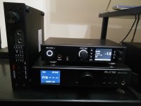
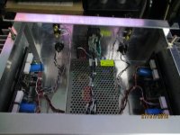
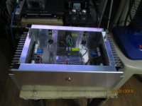
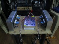
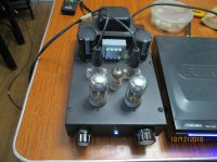
Balanced ACA
balanced ACA....XLR inputs and a SY Impasse clone tube preamp combo....
balanced ACA....XLR inputs and a SY Impasse clone tube preamp combo....
Attachments
balanced ACA....XLR inputs and a SY Impasse clone tube preamp combo....
Impressive!
Did you make your own PCBs (for the ACA)?
Stan
Impressive!
Did you make your own PCBs (for the ACA)?
Stan
yes, two channels in one board....
- Home
- Amplifiers
- Pass Labs
- Amp Camp Amp - ACA