... But there's a setback: the new trim-pots don‘t fit (see pic) — can/should I fix that, or dig out the original parts?
Many thanks
Yes they are the wrong type they are 3386 G types. No way to fit them.
You need the 3386 P type as above. It is confusing, there are 10 or 12 different pin outs...
Very nice layout so far too. Alan
Attachments


Last edited:
Here‘s where I‘m at so far.
It‘s fun and looks good (for a start)
But there's a setback: the new trim-pots don‘t fit (see pic) — can/should I fix that, or dig out the original parts?
Many thanks!
da.
I tried to put some links to images to illustrate, it's hopefully working:
Wiring bliss:
An externally hosted image should be here but it was not working when we last tested it.
Trim-pots, non matching:
An externally hosted image should be here but it was not working when we last tested it.
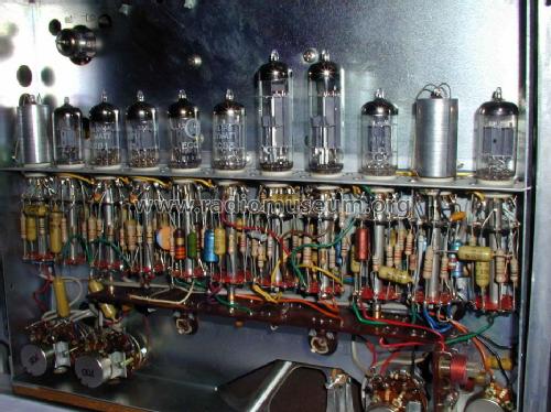
PS My inspiration:
and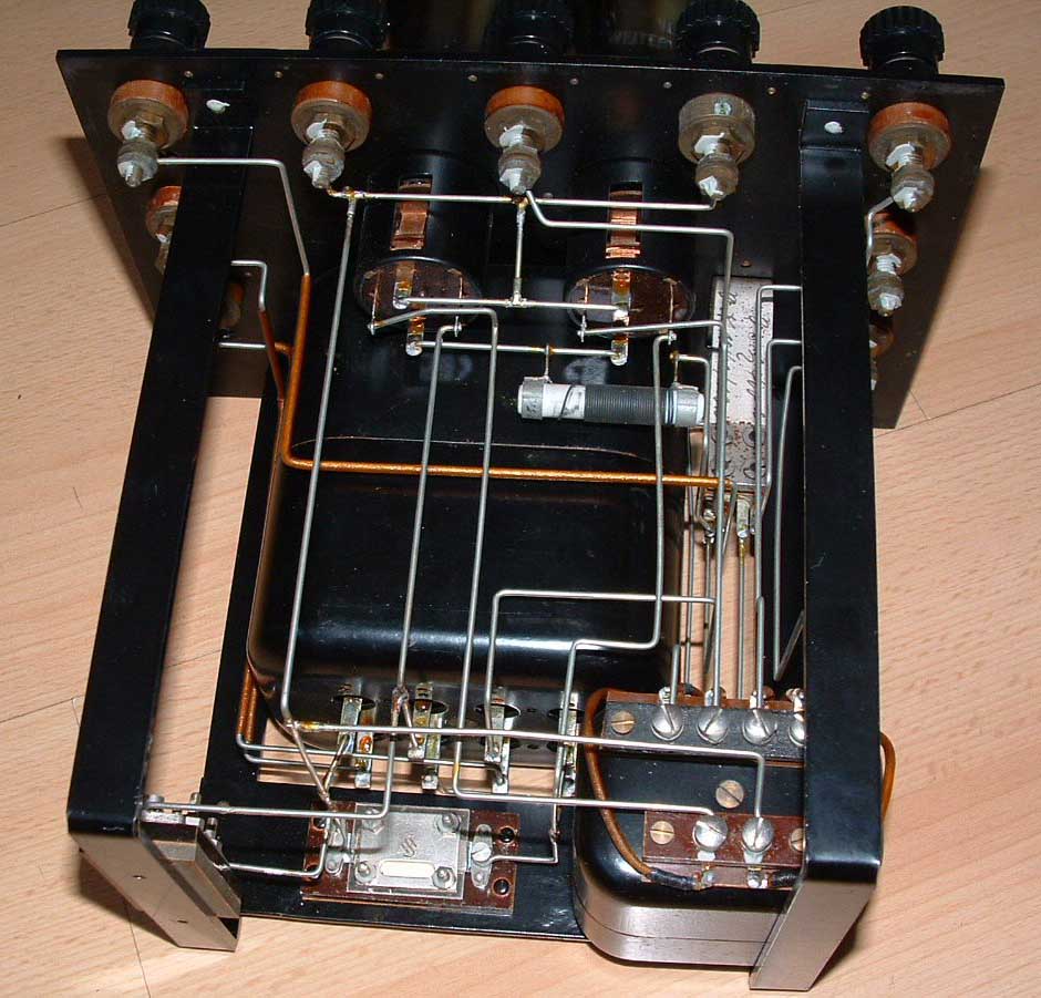
Love your inspiration was trying to do the same with my Korg Nutube with only partial success.


hi,
i have a question regarding to the switch behind
is it possible to install without the switch behind and run in 3 mode(balanced mono or bridge mono and parallel mono)
just follow the way of plugging cable like the guide shown so. for example,
balanced mono ( without switch, step 54)
bridge mono (without switch, step 55)
parallel mono ( additional wire to connect the - output left and right)
You need the switch for 'bridged mono' mode. Step 55 shows the switch in the 'made' up position. (It connects the output of the White channel to the input of the Red channel via the 39k resistor.)
All other modes do not need the switch.
You could replace the switch with a more complicated one to give you 3 positions and therefore three options though.
All other modes do not need the switch.
You could replace the switch with a more complicated one to give you 3 positions and therefore three options though.
You need the switch for 'bridged mono' mode. Step 55 shows the switch in the 'made' up position. (It connects the output of the White channel to the input of the Red channel via the 39k resistor.)
All other modes do not need the switch.
You could replace the switch with a more complicated one to give you 3 positions and therefore three options though.
Which mean I do not need switch for rca input ?
Switch is only for balanced input?so I can ignore the switch and the resistor if I do not need balance input?
Which mean I do not need switch for rca input ?
Switch is only for balanced input?so I can ignore the switch and the resistor if I do not need balance input?
That is what I did, ignored the switch and balanced connector.
We have crossed wires here.
To use the ACA as a Stereo amplifier (RCA inputs) you do not need the switch.
To use the ACA a a mono amplifier with the XLR input (Balanced bridged mode as in step 54) you do not need the switch.
To use the ACA as a mono amplifier in Parallel mode you do not need the switch. (You need to link both the input and both outputs.)
To use the ACA as a mono amplifier with one RCA input (bridged mode as in step 55) you do need the switch.
Simply for 'bridge mode', if you have XLR input (balanced bridge input mode) you do not need the switch.
If you use the RCA input (bridge mode) you need the switch and resistor.
Remember when the switch up it is 'made' or connected. Down is 'open' or dis-connected.
Last edited:
That is what I did, ignored the switch and balanced connector.
but somehow balanced have lower noise, but i do not have balance preamp. i guess i can just follow your way.
We have crossed wires here.
To use the ACA as a Stereo amplifier (RCA inputs) you do not need the switch.
To use the ACA a a mono amplifier with the XLR input (Balanced bridged mode as in step 54) you do not need the switch.
To use the ACA as a mono amplifier in Parallel mode you do not need the switch. (You need to link both the input and both outputs.)
To use the ACA as a mono amplifier with one RCA input (bridged mode as in step 55) you do need the switch.
Simply for 'bridge mode', if you have XLR input (balanced bridge input mode) you do not need the switch.
If you use the RCA input (bridge mode) you need the switch and resistor.
Remember when the switch up it is 'made' or connected. Down is 'open' or dis-connected.
so switch is just for convenient purposes? where u can use switch between xlr and rca bridge with the swicth up and down?
so switch is just for convenient purposes? where u can use switch between xlr and rca bridge with the swicth up and down?
Yep - pretty much.
It's covered in useful detail in the build guide - go to Steps 53-55. The store page for the ACA kit has some good detail around the tech spec section. There's a link about operating modes.
I've found it very convenient to have the switch on hand. Useful in those odd occasions when I've needed a straight-forward stereo amp with RCA inputs. I lent one to a fellow DIY'er to help out with troubleshooting. It's handy and I'm glad that the option to build it in has been considered.
Last edited:
so switch is not necessary in this build?
where u can make it
stereo ( 1 aca)
mono xlr bridge ( 2 aca)
mono rca ( 2 aca)
parallel mono (2 aca)
so if without a switch, i can just plug in whatever mode i wan( follow the guide of 53 ~ 55 ) ? just like what alan have stated ?
where u can make it
stereo ( 1 aca)
mono xlr bridge ( 2 aca)
mono rca ( 2 aca)
parallel mono (2 aca)
so if without a switch, i can just plug in whatever mode i wan( follow the guide of 53 ~ 55 ) ? just like what alan have stated ?
so switch is not necessary in this build?
where u can make it
stereo ( 1 aca) Correct
mono xlr bridge ( 2 aca) Correct
mono rca ( 2 aca) Wrong
parallel mono (2 aca) Correct
so if without a switch, i can just plug in whatever mode i wan( follow the guide of 53 ~ 55 ) ? just like what alan have stated ?
Sorry lifefordota, I did not say that.
To make the RCA 'bridge monobloc' work you have to use the output of the 'white' channel as the input to the 'red' channel. That is done with the 39k resistor you see in step 33 or 34. When you want to use the RCA bridge mode the switch connects the resistor from the white output to the red input.
steep.learning.curve.
part.one.
ok, one and a halve...
Thank you!
part.one.
ok, one and a halve...
Yes they are the wrong type they are 3386 G types. No way to fit them.
You need the 3386 P type as above. It is confusing, there are 10 or 12 different pin outs...
Very nice layout so far too. Alan
Thank you!
Love your inspiration was trying to do the same with my Korg Nutube with only partial success.
View attachment 790395
View attachment 790396
This looks daring, though...
I am a newbie at building and started my Pass amp ACA today. I had a hard time confidently figuring out which resistors were which- the color code on the masking tape for each pack was washed out on a few and hard to determine what it was. I do have a multimeter and checked them all but was not confident that I was understanding the schematic when checking it. I also was confused by the photos of the finished boards - the color bands on some of the resistors was really hard ot determine- blue looks black for instance.
It's be super helpful if there were a reference list that simply indicates which resistors go into which board slots- both by value and by color banding- I don't see this anywhere. I do see the list of the included resistors and their value but it'd be most helpful if they were also referenced to their location on the board.
I ended up putting two wrong ones in, soldered, clipped and then had to de-solder them to get them out.
Is there a detailed youtube vid on soldering the resistors in or a cheat sheet the details which resistor goes into "R7", which go into "R9" etc?
Also, should I be soldering from the top of the board or the bottom?
Thanks ! Looking forward to getting this done right and firing it up !
Hi, can someone point me to the Parts List and instructions for the 1.6 ACA pls, I just bought it and cam running into questions about the correct location for several of the resistors on the board, I see it referenced in the Parts list that some members have posted- is there a link I can go to in order to download it ?
thanks
thanks
Hi, can someone point me to the Parts List and instructions for the 1.6 ACA pls, I just bought it and cam running into questions about the correct location for several of the resistors on the board, I see it referenced in the Parts list that some members have posted- is there a link I can go to in order to download it ?
thanks
Check the ACA 1.6 Build Guide Step #1 .. 😉
I am a newbie at building ...
It's be super helpful if there were a reference list that simply indicates which resistors go into which board slots- both by value and by color banding- I don't see this anywhere. I do see the list of the included resistors and their value but it'd be most helpful if they were also referenced to their location on the board.
Hi acowans,
Astromo has pointed you to the 'Build Guide'. I assume you are using a DIY store kit? If so the part numbering should make sense now with the locations printed on the PWB, matching the parts listing (with values) and schematic in step #1?
DIY Store Team, maybe the documentation in the kit should be updated to include the web link direct to the build guide as one of the first steps?
... Also, should I be soldering from the top of the board or the bottom?
Thanks ! Looking forward to getting this done right and firing it up !
Best to solder the resistors, capacitors and transistors Q3 and Q4 from the back / bottom of the board. If you get it 'right' you should have a nice cone of solder round the component lead on both sides of the board. (See the build guide pictures for good examples.)
The transistors Q1 and Q2 and the wires have to be soldered from the top / component side.
Good luck! Alan
Last edited:
Hi acowans,
DIY Store Team, maybe the documentation in the kit should be updated to include the web link direct to the build guide as one of the first steps?
The link to the build guide is the 4th bullet point in the first paragraph on the store's ACA kit page.
I doubt there's much can be done to improve the current layout.
No argument there, but there is no direct link to the Build Guide on the sheet included with the kit (not on the one I have anyway) in fact the Build Guide only gets mentioned in para 12 and then no link is included?
There is reference to links for the DiyStore and this forum page, which might get you to it, but clearly it has been missed on a few occasions...
I was simply suggesting that reference to the Build Guide was added to the sheet that comes in the kit and make its existence more prominent.
Perhaps,''Congratulation on your choice.... the full V1.6 kit Build Guide is here Amp Camp Amp V1.6 Build Guide - diyAudio Guides ...''
or just add a paper strip with, ''Now see the step by step Build Guide here: Amp Camp Amp V1.6 Build Guide - diyAudio Guides and enjoy building your kit''.
Last edited:
- Home
- Amplifiers
- Pass Labs
- Amp Camp Amp - ACA