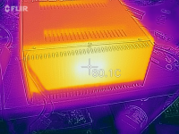
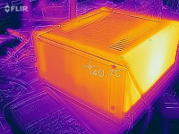
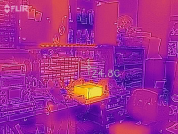
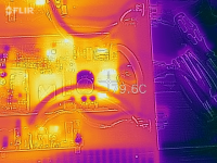
I built a stereo ACA using a variant of that chassis (no knob) and the previous gen ACA boards with an internal 24V power supply and mine runs hot: 60°C at 25°C ambient. If you run an external supply you might be ok. An external 20V should run it even cooler. The latest ACA boards have the FETs placed further apart, and that should help with the spreading the heat across more of the heat sink. This chassis has fins that are only 1” tall/deep as compared to 2”, but the heat sink has more area than stock. To reduce the case temperature I’m planning to mill vents in the solid bottom cover, to improve internal convection cooling (the top is vented). One other caveat is that there isn’t much meat on the heat sink so it was difficult to tap blind holes and have enough thread engagement for the standoffs. If you’re ok seeing the standoffs through the heatsink then it’s a lot easier to tap a through-hole.
Here’s my ACA:
Pictures of your diy Pass amplifier
Here’s my ACA:
Pictures of your diy Pass amplifier
Attachments
Last edited:
Olen, to improve convection of your unit you should consider adding legs that leave about an inch clearance from the surface where it lies to the bottom of the unit. This will increase the ease for air intake into the enclosure. You may want to consider milling or drilling the top cover as well as the bottom to increase convection.
Input cap as high pass
I would like to create a 1st order high pass filter for the ACA with a rolloff starting at 130Hz. Based on the input impedance of 10k I come up with a value of 0.12uF for the cap. Rather than adding another cap to the input can I change the value of C3 to achieve the same rolloff? It looks like the input impedance is set by R11 which comes before C3 so I am not sure if this is possible and how to calculate it?
I would like to create a 1st order high pass filter for the ACA with a rolloff starting at 130Hz. Based on the input impedance of 10k I come up with a value of 0.12uF for the cap. Rather than adding another cap to the input can I change the value of C3 to achieve the same rolloff? It looks like the input impedance is set by R11 which comes before C3 so I am not sure if this is possible and how to calculate it?
Years ago, I learned enough about filters to make good crossovers for my speakers. I vaguely recall that the 1st order filters cut off the signal gradually while higher orders cut it off rapidly. Do you really want a first order filter?
I currently have a line level 1st order between my pre and power amp and am happy with the result using a full range speaker (FF105WK) and sub. A 12db or higher slope seems to add more complexity and is it possible with the ACA at a passive line level? I have also contemplated adding in an active cross over like that offered by Rod Elliott but this seems in contrast to the simple philosophy of the ACA, a philosophy that appeals to me. I did look at a speaker level filter but this seems expensive and compromised due to the big impedance spike that this speaker has around this frequency.
All speakers have filters (crossovers) to accomodate the usable frequencies of their drivers. The idea is to have each driver work only in the portion of the spectrum where it has a flat response. These are all filters. Commercial equipment generally tend to skimp on the crossover filters but they are there, inside the speakers.
I am sorry but I have never done or researched filters betweem amps and preamps, this is new to me. However I can see filtering the signal arriving from digital sources to eliminate junk over a high level.
As far as your speakers go (your full range FF105WK plus sub), the full range driver, like every other driver, has its own idiosyncracies and its own optimal flat range. A good crossover has to be tailored to the specific driver you are dealing with, whatever it may be.
The 130 Hz y9ou mention is subwoofer territory, you could just cut the signal off at a higher frequency, avoiding the impedance spike, and let the subwooofer handle the lows. I assume the your sub can handle frequencies below 1000 HZ level.
All speakers have filters (crossovers) to accomodate the usable frequencies of their drivers. The idea is to have each driver work only in the portion of the spectrum where it has a flat response. These are all filters. Commercial equipment generally tend to skimp on the crossover filters but they are there, inside the speakers.
.......
The 130 Hz y9ou mention is subwoofer territory, you could just cut the signal off at a higher frequency, avoiding the impedance spike, and let the subwooofer handle the lows. I assume the your sub can handle frequencies below 1000 HZ level.
No crossovers in these speakers, it's just one driver in a box so nothing to cross between and I built them so I know it is just wires between the binding posts and speaker.
The plate amp on my sub has a max low pass of 140Hz. I am looking to keep these in place and do not want to impact the speaker efficiency since I am only dealing with 8 watts from the ACA and this is my main system in a small living room hence the desire for a simple line level solution. To expand a bit I plan to use an AKSA Lender preamp as a front end. Appreciate the feedback.
Thanks for the tip OC11, I had the very same thought so I added a 3/4” wood spacer underneath the existing feet, which only helped lower the heatsink slightly, less than 1°C if I remember correctly. You can see the spacer in the picture showing the front of my amp.
Hi spiggs,
A single pole (6dB/oct) high RC pass filter can be calculated from the equation: C=1/(2pi*R*f), assuming you have a relatively low impedance source. The issue with changing C3 is that it’s ‘driven’ through a 10k resistor (R11) and R12 is in the feedback loop, so the source impedance isn’t so straight forward (but the effect of this ‘should’ be negligible). If you want to calculate the HP frequency for C3 then the R in the equation is R10 plus about half (maybe?) of P1, so about 335k. To get 130Hz you’ll need a C of 3.6nF (not a common value so you might have to parallel two values). In my amp I used a 1uF Wima for C3 and the roll off is below 20Hz.
Instead you might want to try swapping out C1 with a lower value higher quality cap. In this is case your R is the speaker impedance which looks to be 8 ohms, so 153uF would give you 130Hz. A smaller value C1 should also reduce the turn on/off thump. Or if you don’t want to swap out C1 just place the 150uF cap in series with your speaker. If you have room and the money you could even try a film cap which should be a noticeable improvement.
Here’s one example I found:
Solen, 150uf, 400V - Meniscus Audio
....
Hi spiggs,
A single pole (6dB/oct) high RC pass filter can be calculated from the equation: C=1/(2pi*R*f), assuming you have a relatively low impedance source. The issue with changing C3 is that it’s ‘driven’ through a 10k resistor (R11) and R12 is in the feedback loop, so the source impedance isn’t so straight forward (but the effect of this ‘should’ be negligible). If you want to calculate the HP frequency for C3 then the R in the equation is R10 plus about half (maybe?) of P1, so about 335k. To get 130Hz you’ll need a C of 3.6nF (not a common value so you might have to parallel two values). In my amp I used a 1uF Wima for C3 and the roll off is below 20Hz.
Instead you might want to try swapping out C1 with a lower value higher quality cap. In this is case your R is the speaker impedance which looks to be 8 ohms, so 153uF would give you 130Hz. A smaller value C1 should also reduce the turn on/off thump. Or if you don’t want to swap out C1 just place the 150uF cap in series with your speaker. If you have room and the money you could even try a film cap which should be a noticeable improvement.
Here’s one example I found:
Solen, 150uf, 400V - Meniscus Audio
The problem with using C1 to filter is the impedance curve of the speaker spikes around that frequency so the cutoff does not act like a stable 8 ohm value would predict. Although thinking about it I could probably reduce the value of C1 considerably and stay outside of the range that would impact anything below 130Hz even with the varying impedance.
Thanks for the calculation for C3, sounds like I could start with 3.6nF and experiment a bit to get there. Or just put the 0.12 uF on the input and be happy that I reduced the value of C1 and replaced it with a higher quality cap.
I would stick with doing the filtering on the input side. Note that the feedback is taken from the output side of the 3300uf cap. It looks to me like using a 150uf cap on the output will not be an effective way to reduce LF output. If you put the cap on the input then you will roll off the signal before the amp which increases your dynamic range and makes the ACA’s 5 watts go further. Sure, you are putting another cap in the signal path, but it is easy to do and reverse if you don’t like the results.
Spiggs I just searched for your driver's response and impedance charts. Found FF165WK and FF125WK, not the FF150WK, same family I presume. You can use these drivers as subwoofers or cut them off below 200 Hz. The nice flat response range starts getting ratty with these in the not so high ranges. Both drivers have problems off center, greater at 60 degree than 30. If you want to avoid this (non flat off center response curve) you need a tweeter over the 5K to 7K range. If you are willing to live with the off center issues without a tweeter, the 0 degree response is fairly good with both of these up to 7K. Above 7000Hz the response is not flat.
Impedance does spike heavily at 50 Hz to around 50 ohms with the 165, and at 65 Hz to around 65 ohms with the 125. Both of these have a range of stable response at 8 ohm impedance from about 200/250 Hz to about 1000 Hz, then the impedance starts climbing. By 5000 Hz you are around 12 ohms with the 165, and about 10 ohms with the 125. The readings I am giving you are done by eyeballing the graphs.
Everything in life is a compromise. I would consider adding a preamp to your ACA and leaving your speakers as they are.
Last edited:
Spiggs
What enclosure are you using with your FF105WK?
Ricardo
mFonken
I would stick with doing the filtering on the input side. Note that the feedback is taken from the output side of the 3300uf cap. It looks to me like using a 150uf cap on the output will not be an effective way to reduce LF output. If you put the cap on the input then you will roll off the signal before the amp which increases your dynamic range and makes the ACA’s 5 watts go further. Sure, you are putting another cap in the signal path, but it is easy to do and reverse if you don’t like the results.
The plan is to have the input filtered whether through an additional cap or tweaks to C3. Given that would there be any harm in reducing the size of C1 to 150uF or even 220uF?
Question clarification about C1
I’m a newbie still trying to understand audio circuits but earlier discussions about C1, and I believe if memory serves me correctly even 6L6 commented C1 had nothing to do with audio signal ?. It’s only purpose was to filter out DC ?. Enlightening me with information about any additional purpose of C1 I’m trying to learn as much as possible in the shortest period of time so I too can tinker with this little circuit And learn more.
The plan is to have the input filtered whether through an additional cap or tweaks to C3. Given that would there be any harm in reducing the size of C1 to 150uF or even 220uF?
I’m a newbie still trying to understand audio circuits but earlier discussions about C1, and I believe if memory serves me correctly even 6L6 commented C1 had nothing to do with audio signal ?. It’s only purpose was to filter out DC ?. Enlightening me with information about any additional purpose of C1 I’m trying to learn as much as possible in the shortest period of time so I too can tinker with this little circuit And learn more.
Last edited:
I’m a newbie still trying to understand audio circuits but earlier discussions about C1, and I believe if memory serves me correctly even 6L6 commented C1 had nothing to do with audio signal ?. It’s only purpose was to filter out DC ?. Enlightening me with information about any additional purpose of C1 I’m trying to learn as much as possible in the shortest period of time so I too can tinker with this little circuit And learn more.
From my understanding having a cap on the output provides the DC filter and the size of the cap will impact low frequency roll off. If I put 3300uF into a crossover calculator at 4 ohm I come up with a rolloff at 24hZ or 12hZ at 8ohm. I am very much a newbie as well so this is all the blind leading the blind. Don't have any idea if there are other factors impacting the feedback loop.
C1 couples the amplifier output to the speaker and it is needed to prevent continuous DC current flowing in the speaker.
The ACA output is at a nominal 12 volts DC and so without the cap a current of I= V/R would flow, which means for an 8 ohm speaker means a current of 12/8 or 1.5 amps. Result, one burned out voice coil.
The cap forms a 1st order filter in combination with the load, or at least would were it not for the fact that the feedback is taken from the output side of the cap. This technique means that the amplifier tries to maintain the wanted output voltage as frequency falls.
The advantage of this is that the caps shortcomings are compensated for, and we can also use a smaller value cap while still maintaining a flat low frequency response.
The disadvantage is that as frequency falls, the amp works harder to maintain the output voltage and so will clip earlier at low frequency compared to the midband.
So as always its a compromise, and 3300uF is a good value for operating into most realistic loads that will be encountered.
I'm not sure how a preamp helps tbh ")
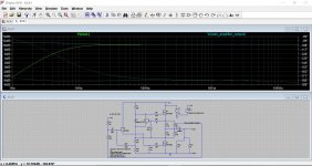
This shows how enclosing the cap within the feedback loop maintains the response, but also how it achieves that at the expense of headroom.
These images should help explain how it works. There are two points being monitored, the normal speaker output from after the cap and also the main amplifier output before the cap.
Image 1 is a conventional feedback take-off point from before the cap. It may seem unexpected that the main amplifier output has a slight rise in amplitude at LF, however this is caused by the fact that the load current is reducing (due to the caps reactance) and that in combination with the ACA's fairly high output impedance manifests itself as an increase output.
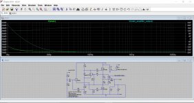
Image 2 shows the feedback connected as per the ACA design. Notice how the speaker output is now maintained at an approximately flat response, but also note how the main amplifier output (before the cap) rises almost exponentially in order to achieve this.
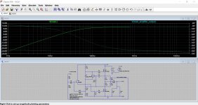
Image 3 shows the cap reduced in value by a factor of 10 i.e it is now just 330uF. The feedback is now connected conventionally and the LF roll off is significant.
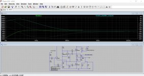
Image 4 is once again back to the ACA feedback connection method and we can see how the amplifier main output rises to counteract the increasing impedance offered by C1 as the frequency falls. The output is maintained down to approximately 4Hz, but at what cost ? The cost is the massive output needed before the cap, and that increase needed is now so great that the ACA would run out of headroom. Look at the 36db maximum level needed to maintain the ACA's nominal gain at the speaker terminal.
This shows how enclosing the cap within the feedback loop maintains the response, but also how it achieves that at the expense of headroom.
These images should help explain how it works. There are two points being monitored, the normal speaker output from after the cap and also the main amplifier output before the cap.
Image 1 is a conventional feedback take-off point from before the cap. It may seem unexpected that the main amplifier output has a slight rise in amplitude at LF, however this is caused by the fact that the load current is reducing (due to the caps reactance) and that in combination with the ACA's fairly high output impedance manifests itself as an increase output.
Image 2 shows the feedback connected as per the ACA design. Notice how the speaker output is now maintained at an approximately flat response, but also note how the main amplifier output (before the cap) rises almost exponentially in order to achieve this.
Image 3 shows the cap reduced in value by a factor of 10 i.e it is now just 330uF. The feedback is now connected conventionally and the LF roll off is significant.
Image 4 is once again back to the ACA feedback connection method and we can see how the amplifier main output rises to counteract the increasing impedance offered by C1 as the frequency falls. The output is maintained down to approximately 4Hz, but at what cost ? The cost is the massive output needed before the cap, and that increase needed is now so great that the ACA would run out of headroom. Look at the 36db maximum level needed to maintain the ACA's nominal gain at the speaker terminal.
Attachments
I'm not sure how a preamp helps tbh
This shows how enclosing the cap within the feedback loop maintains the response, but also how it achieves that at the expense of headroom.
These images should help explain how it works. There are two points being monitored, the normal speaker output from after the cap and also the main amplifier output before the cap.
Image 1 is a conventional feedback take-off point from before the cap. It may seem unexpected that the main amplifier output has a slight rise in amplitude at LF, however this is caused by the fact that the load current is reducing (due to the caps reactance) and that in combination with the ACA's fairly high output impedance manifests itself as an increase output.
Image 2 shows the feedback connected as per the ACA design. Notice how the speaker output is now maintained at an approximately flat response, but also note how the main amplifier output (before the cap) rises almost exponentially in order to achieve this.
Image 3 shows the cap reduced in value by a factor of 10 i.e it is now just 330uF. The feedback is now connected conventionally and the LF roll off is significant.
Image 4 is once again back to the ACA feedback connection method and we can see how the amplifier main output rises to counteract the increasing impedance offered by C1 as the frequency falls. The output is maintained down to approximately 4Hz, but at what cost ? The cost is the massive output needed before the cap, and that increase needed is now so great that the ACA would run out of headroom. Look at the 36db maximum level needed to maintain the ACA's nominal gain at the speaker terminal.
Thank you Molly for the visual and the explanation by answering one question of course we all know that leads to 10 more questions.
I think I’m grasping the basic concepts here in one of three ways you can perform the desired outcome correct me if I’m wrong in my understanding. 1: you can change the signal path capacitors for your low pass and your hi Pass inside to amplifier. 2: You can change the frequency’s to your speakers through crossovers from my reading and other peoples comments has its pluses and minuses and kind a complex and complicated for newcomers. 3: LXmini , after attending my first Burning AMP event this year and hearing about that LXmini seems like a easier and more convenient way of experimentation if you want to bi-AMP or try-amp or even quad-AMP?.
I love my hi efficiency full range speaker horn loaded i’ve built specifically for this ACA. But now that repressed locked away teenager in me would like to build an experiment with three or four amplifiers one for each driver in a cabinet.
So what I’m getting at with LXmini be a good starting point for newbie to experiment easily with multiple amplifiers to a speaker cabinet. Then after gaining that knowledge possibly taking it a step further and finding the corrections of capacitors resistors and chokes and bring that knowledge to transfer it to your specific amplifiers internally and eliminating the LXmini ?.
Last edited:
- Home
- Amplifiers
- Pass Labs
- Amp Camp Amp - ACA