10V if using 19V PSU
12V if using 24v PSU
🙂 🙂 🙂 The only stupid question is the one you don't ask. 🙂 🙂 🙂
12V if using 24v PSU
🙂 🙂 🙂 The only stupid question is the one you don't ask. 🙂 🙂 🙂
Last edited:
I’m ready to plug in 1.6. Please remind how to bias and what voltage to get it to. What setting do I use on multimeter. I know. Newbie
Use the DC Voltage setting, choose the next range up from what you are trying to measure - for instance, if it’s 12VDC, your meter may have a 20V range.
Place one meter probe on the chassis (or “ground”), and the other on the centre pin of Q1, the big transistor near the square blue potentiometer, just don’t slip and short anything out 🙂 Adjust the potentiometer with a flat bladed screwdriver until you get to 12.0 volts (if using a 24vdc power supply). Be careful, the potentiometer is extremely sensitive to movement, and there is a time lag between moving it and getting a steady voltage reading. Turn the potentiometer just a VERY tiny bit at a time, then wait perhaps 30 seconds for it to settle before the next adjustment. The voltage reading may also change as the amp gets up to its normal operating temperature. Ensure final adjustments are done after the amp has warmed up for half an hour or so.
I'll take a swat: If you reverse power supplies does it do this?
Hello, I built a pair of ACAs. They both bias fine and work fine. I am curious about one thing though. When I turn off one of the amps, the LEDs will immediately go dark. When I turn off the other amp, the LEDs will slowly fade to dark. I am wondering if this points to something I may have done incorrectly. I double checked all wiring and they are the same.
Thanks,
Alan
Hello,
New problem for my ACA 1.6. Why are both irfp240 mosfets not heating up? Need help, please.
Mooly, Thank you very much for your all the help. 🙂
New problem for my ACA 1.6. Why are both irfp240 mosfets not heating up? Need help, please.
Mooly, Thank you very much for your all the help. 🙂
I will take some pictures and post them.
That was post #5308.
And Mooly, as you rightly stated has been extraordinarily helpful.
Do you mind posting several close up hi rez pics of the ACA build that is troublesome?
Thank you!
Anand.
The Amazing ACA
Received the parts last Monday (20th). Beautifully packaged and complete.
Assembled both boards with ease following circuit diagram and parts list on Tuesday. Both boards biased and installed in the wonderful Italian chassis on Wednesday. Fired it up Thursday and have been playing it ever since. This amp is a masterpiece of simplicity and truly lovely performance.
Thank you all to those involve in its creation.
Graeme
Hello,
New problem for my ACA 1.6. Why are both irfp240 mosfets not heating up? Need help, please.
Mooly, Thank you very much for your all the help. 🙂
As always, do a DC voltage check at the various nodes. Something should show up and reveal a problem. Exact voltages will vary a little (and vary depending on where you have the bias set) but some major discrepancy should show if your FET's are cold.
(didn't you have this issue earlier and it mysteriously healed up ? and I suspected broken print somewhere)
Attachments
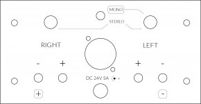
Finally I made some progress for the second version of the backpanel engravings. Adjustments were made with the help of you.
What do you think of it now?
I like it!
I like it a lot! Much cleaner and readable than the previous iteration. Looks great!...What do you think of it now?
May I ask why you moved away from the double-outline font? I like this one better, but I thought that was a requirement of the laser in order to etch the outlines better an with more presence and readability. But if this will work also, then... yes, much Nicer!
Finally I made some progress for the second version of the backpanel engravings. Adjustments were made with the help of you.
What do you think of it now?
Awesome! I actually like the mono designations, specifically on the speaker outputs (black terminals). As you show correctly there is a positive and a negative with that too.
Best,
Anand.
The thick wires, which are 16 Ga (usually Red and Black) are used from the PCBs to the speaker terminals. Everything else is the thinner wire which is 22 Ga. and now is all solid core.
I sat with Nelson while he looked up the power capacity and loss of the 22 Ga thin solid wire for the PSU jack wiring and it is plenty to handle the load, considering what a short run the Power wires are. And consider that the wires from the PSU to the amp jack aren't exactly massive! The reason you would want to use the thinner wire is that the DC jack and power switch have very small holes and the 16Ga wire won't fit through these holes. However in the future we will include more wire of both types so you have the option.
Here's a link:
Single Conductor Hook-Up Wire in the Speaker Components Department at Parts Express | 1900
Like Zer0p0intZer0, I'm confused about where to use the heavier gauge hookup wire (red and black in my supplied kit, although the pictures provided recently show blue and black heavy wires). I would think (and it LOOKS like) that the heavier gauge wire should be used for the power supply distribution and for the output to the speaker terminals. And it looks like the red, green, blue and white smaller gauge wires should be used for everything else. It would be good to know what the gauges are in case we have to go out and find more wire (or if we want to customize the colors we use for particular parts of the circuit).
Last edited:
Thank you dear diy friends! When I laser I will show the results. First I will try a sample the the inside of the panel. When all is correct I will post a pdf. This way other diy’rs or HIFI2000 can use it for the next badge. You can even send a back panel to me and I will engrave it for you. Price will be a little shipping and handling.
As for your question RafaPolit. The first drawing was made in 3D CAD. I converted that to a 2D dxf file and used that in Adobe Illustrator. This way I can use layers which the laser will detect: cut lines, engraved hair outlines and/or engraved area’s ie thicker fonts.
As for your question RafaPolit. The first drawing was made in 3D CAD. I converted that to a 2D dxf file and used that in Adobe Illustrator. This way I can use layers which the laser will detect: cut lines, engraved hair outlines and/or engraved area’s ie thicker fonts.
Last edited:
That was post #5308.
And Mooly, as you rightly stated has been extraordinarily helpful.
Do you mind posting several close up hi rez pics of the ACA build that is troublesome?
Thank you!
Anand.
Hi Anand,
Tried it on post #5308. When I was asked to provide url I can't. It is not like uploading pics on ebay. But I will try again.
Thanks a lot.
I've just finished my first ACA 1.6 and I ran into a problem now. Maybe this was already answered but I really don't want to read 549 pages of posts, hoping the answer can be found somewhere. So I just ask the question.
When I turn on the amp, all seems good. There is a very small hiss through my 104 db speakers. However, when I turn on my pre-amplifier, I hear a very loud "hum/static". When I play music I actually hear it through the loud noise. The noise doesn't become louder when I increase the volume, the music does. Is this some kind of grounding problem?
Can somebody help me to identify and correct the problem?
Thank you
Hi Anand,
Tried it on post #5308. When I was asked to provide url I can't. It is not like uploading pics on ebay. But I will try again.
Thanks a lot.
Easy to add pictures.
Try this way, Start typing a message first, then scroll down to 'additional options' from this pane. (Between the area you type in and the previous posts.)
Find Attach File & click on Manage Attachments. Another window will open. Then click on the top 'Choose File', find the picture you want to add and click open.
Then once the file is identified, click 'upload'. Done.
Alan
- Home
- Amplifiers
- Pass Labs
- Amp Camp Amp - ACA