Rafa ....... considering how ACA is simple , is there posibility to make it from parts sourced locally ?
hey , scrapyards are perfect for obtaining parts for funny cases
then PSU can be made in myriad ways , all of them cheap
mosfets - practically anything can work here , with small sonic compromise or even without
Rafa, please see this post, if you missed it.
Thanks for all the replies.Exactly this.
Where there's a will there's a way.
This mad simple circuit should easily be parts sourced locally, and wired point to point.
Short answer is no, local parts availability is extremely difficult, and, when available, only the worst / cheapest option. This is purely a price market. You cannot ever find something beyond the cheaper option, as no one would buy it. So factor that into RCA connectors, binding posts, etc. And then, the linear transistors, which are not an option.
I'll try and see if someone traveling from the US can bring some of those. Chasis are obviously the other issue, nice classy looking options are a no-go.
Again thanks, I really appreciate all the good will and suggestions. Probably you are not all that familiar with limited markets with little variety and availability, so probably this sounds like whining. I'll look into options and report back hopefully with a success story.
Best regards,
Rafa.
I did take time to set a way up to use a few unmatched backup Semisouth R100 I have in the ACAs. I didn’t know if I wanted them to stay in the ACA, so I made some sockets with extension harness’ for them to connnect to the PCB which I relocated to the floor of the case.
The way I see it, only Q1 should be replaced with the SemiSout's... Q2 is supposed to be a low noise current source.
Is there a noticeable difference in sound between IRFP240 and SemiSouth? I think the latter one should sound better... but would love to hear your opinion.
chrisb / bm2352 - I'm also considering combining two ACA's into one chassis. Interesting point about the switching power supply. Are you suggesting placing it inside the amp chassis? I'd always understood switching supplies to be noisy. Is this one quiet enough that it's not an issue ? Did Nelson Pass spec the outboard supply for the ACA purely for cost reasons or was noise reduction part of the consideration?
The switching mode supply could go inside the amplifier, but at that moment you'll have to start dealing with mains voltages (I'd expect you'll need an IEC connector at the back, and a mains 110/230V AC rated switch); this could be lethal. However, a short 24V DC wiring (or even a copper bus-bars) to both PCB's, straight from the SMPS, could bring some major sound benefits.
Over at CA there is a lot of talk about DIY JSSG cable and shunting wall ward power supplies. See topic SMPS and grounding. It's an easy mod. Done this with LPS-1.
Over at CA there is a lot of talk about DIY JSSG cable and shunting wall ward power supplies. See topic SMPS and grounding. It's an easy mod. Done this with LPS-1.
Maybe the latest 24V version of the ACA's SMPS has some sort of "shunting" done already... I would assume that a "wide-band" capacitor combo (0.1 and 0.01uF in parallel, scattered around the SMPS), would provide an adequate AC shunting of the 24V negative side, via ground pin at the mains side / mains input. This would need to be checked...
The way I see it, only Q1 should be replaced with the SemiSout's... Q2 is supposed to be a low noise current source.
Is there a noticeable difference in sound between IRFP240 and SemiSouth? I think the latter one should sound better... but would love to hear your opinion.
Yes replacing only Q1 with Semisouth was the answer I received when I brought the subject up several pages back before things got crazy with all the preorder inquiries.
I am working on wiring up the second monoblock case now. Since I made and integrated sockets to plug in the Semisouth and IRF240 and mounted them with silicon pads it will be easy to swap them in order to compare using one or the other at Q1. Hopefully I don’t have any issues with durability of the sockets as I cut up some Radio Shack 18 pin IC sockets to make them.
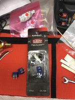
Chromenuts - what is the pitch spacing on those little blue terminal blocks in your assembly photos a few posts back, and from where were they sourced?
Yes replacing only Q1 with Semisouth was the answer I received when I brought the subject up several pages back before things got crazy with all the preorder inquiries.
Not much value replacing Q2, as it is a low gain current source. Actual
listening reveals little or no difference.
I've authored a page for you that details where you can get all the parts to bring your ACA aesthetic from V1.5 to V1.6. It also has the information on bringing a V1.0, V1.0B or V1.1 PCB up to current spec / able to use the new PSU.
ACA Upgrade Information – diyAudio Store
As for the black faceplate, you could order a new chassis and sell the old one in the swap meet or I could speak to Gianluca about adding yet another custom SKU to their system... remember the grass is always greener on the other side of the fence.
Hi, sorry I'm a little late to the conversation... The link you provided got some random brain firings going, which brings me to my questions:
What is the purpose of an XLR connector for the ACA input - when one side of the ACA input is grounded? Doesn't that kind of defeat the purpose of a balanced input? Or is it more a stereo single input (L G R) rather than an actual balanced signal (+ G -)? Did I miss the part where this was discussed? If it is the it is a stereo input, we should be careful not to call it balanced (my presumption is that it is a stereo input, based on there being just one XLR on the back of the ACA chassis, as seen in the photos).
Also, the pre-order web page implies using two ACA in a bridged configuration (The button labeled: "Buy two complete kits - (Build balanced monoblocks with twice the power)" seems to imply that) - did I misunderstand that, or is there a plan for making a bridged ACA (2 boards per chanel)? That could be useful for matching a less efficient Sub to a nice set of efficient full range speakers.
Making a bridged amp out of two separate amps is easy with floating inputs and outputs, but these are both ground referenced in the ACA. Is there a thread or a set of posts discussing this option, or are you paralleling the amps, rather than bridging? If paralleling (is that a word?), is there a small (ohm-wise, probably half an ohm, 5W or more) to help balance the two when driving a single speaker?
Lots of questions, hopefully there are easy answers...
Can IRFP460 be used?
Correcting: I wanted to say replace the IRFP240 with the IRFP460.
I have some original irfp460. Can I use them to replace irfp250?
Correcting: I wanted to say replace the IRFP240 with the IRFP460.
Lots of questions, hopefully there are easy answers...
In the ACA 1.5 Illustrated building guide it is shown in post no. 7 and forward how the ACA is bridged using XLR and RCA input.
They have common GND as far as I can see. My old NAD 3150 could also run in bridged mode. It had two PSUs.....one for each channel but also with common ground. But the GND is not used for connecting the speakers (Red speaker terminals on the ACA). Two Black terminals are used to connect to the speakers in bridged mode. But you better have a look at the thread......to get it from the "source"......
Impedance of output coupling
Impedance of output coupling
<snip> Interesting that the output level is only about 0.5 dB down at 10 Hz in 8 ohm when the impedance of the capacitor is relative high at 10 Hz. It must be the NFB that lowers the ouput impedance.
Maybe my setup can output more power at the lower frequencies......will see.....first it needs to be tested at see if it work at all.....but so far so good......
Impedance of output coupling
Last edited:
Newbie here. I built my ACA mono blocks back in 2016. It was my first electronic build and they worked the first time I plugged them in. Love the sound! I followed the instructions and photos, I really enjoyed the build. I recently pre ordered the upgraded power units for my ACA mono blocks. I sent Jason an e-mail with further questions and he promptly replied.. thanks Jason!! I have a PCB Amp Camp 1B with the R 15 2.2K resistor installed.
My question is the R12 68.1K ohm 0.4W resistor in the PCB 1B now. . In order to use the new power units for the mono blocks they recommend to reduce the value of the resistor to 39.2 K ohm. I imagine it would be 0.4 watts like the 68.1K in there now, is this correct? I just don't want to screw anything up replacing the R12 with an incorrect wattage for the 39.2 resistor. When I went on to the Digi-Key site there were all types of 39.2 K resistors with different watts. Thanks for any help from this newbie...
My question is the R12 68.1K ohm 0.4W resistor in the PCB 1B now. . In order to use the new power units for the mono blocks they recommend to reduce the value of the resistor to 39.2 K ohm. I imagine it would be 0.4 watts like the 68.1K in there now, is this correct? I just don't want to screw anything up replacing the R12 with an incorrect wattage for the 39.2 resistor. When I went on to the Digi-Key site there were all types of 39.2 K resistors with different watts. Thanks for any help from this newbie...
I see the dampening factor as 0.7 for 4 ohms. That implies output impedance is over 5 ohms. Bridged is double that.
Ok, finally caught up. It looks like it's a floor wax AND a desert topping (bonus points for those who get the reference). The necessary details were in the build guide, but down around step 40 or so. I got bored and wandered off before that, having just built one myself in a Dissapante 2U chassis.
The XLR connector could be used for a (L G R) stereo input, running one amp per channel, or as an actual Balanced Input (+ G -) and use the pair of amps in bridged mode, as one channel per amp. A rather versatile arrangement, and one I'm ashamed I didn't notice straight up. I knew I purchased 2 extra kits at BA17 for a reason... 8)
The XLR connector could be used for a (L G R) stereo input, running one amp per channel, or as an actual Balanced Input (+ G -) and use the pair of amps in bridged mode, as one channel per amp. A rather versatile arrangement, and one I'm ashamed I didn't notice straight up. I knew I purchased 2 extra kits at BA17 for a reason... 8)
Might shed some light on your question.
Since balanced cables carry an inverted signal then you are feeding each side of the amplifier with 1/2 of the balanced signal.
For the speaker output, you use the "negative" side of each amplifier.
Thus, you need two ACA's because you are making the amplifier a Mono Block. (If you are listening in Stereo, that is)
It works very well. And the sound is unbelievably clear! If you have efficient speakers - a watt is an incredible amount of sound out of these amps.
Hope that helps!
If it is the it is a stereo input, we should be careful not to call it balanced (my presumption is that it is a stereo input, based on there being just one XLR on the back of the ACA chassis, as seen in the photos).
When you use the amplifier in the balanced configuration - you use the positive side of each channel's unbalanced input.Hi, sorry I'm a little late to the conversation... The link you provided got some random brain firings going, which brings me to my questions:
What is the purpose of an XLR connector for the ACA input - when one side of the ACA input is grounded? Doesn't that kind of defeat the purpose of a balanced input? Or is it more a stereo single input (L G R) rather than an actual balanced signal (+ G -)? Did I miss the part where this was discussed?
Since balanced cables carry an inverted signal then you are feeding each side of the amplifier with 1/2 of the balanced signal.
For the speaker output, you use the "negative" side of each amplifier.
Thus, you need two ACA's because you are making the amplifier a Mono Block. (If you are listening in Stereo, that is)
It works very well. And the sound is unbelievably clear! If you have efficient speakers - a watt is an incredible amount of sound out of these amps.
Hope that helps!
If it is the it is a stereo input, we should be careful not to call it balanced (my presumption is that it is a stereo input, based on there being just one XLR on the back of the ACA chassis, as seen in the photos).
Chromenuts - what is the pitch spacing on those little blue terminal blocks in your assembly photos a few posts back, and from where were they sourced?
LOL...wasn’t sure what you were talking about and had to look back. I was going to use those for my input and output connections, but just soldered them to the board instead.
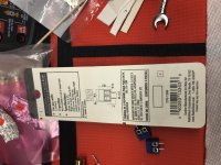
They are 5 mm pitch and came from Radio Shack...part number 276 1388. The local shop closed down last year by me and I bought about half of their component storage cabinets along with contents.
I’m sure others did the same and you can find them online, but also there must be plenty of similar options from Mouser or Digi Key.
Attachments
Ok, finally caught up. It looks like it's a floor wax AND a desert topping (bonus points for those who get the reference).
SNL, back in the day. Thanks for that. 🙂
In an effort to keep this "general" ACA thread clean and timeless, I have moved a number of posts that ask specific questions about the 1.6 kit to their own thread. If you have 1.6 specific questions, please post them in this thread:
FYI: Pre-orders have closed early. Please see: Amp Camp Amp Kit V1.6 - Pre-Order Status Page – diyAudio Store. To be notified about the next batch please use the "Email me when available" button on the Amp Camp Amp product page.
Last edited:
- Home
- Amplifiers
- Pass Labs
- Amp Camp Amp - ACA