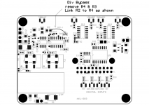
Div Bypass
Slow means Fs 22/24.xx going into a device configured for 45/49.xx
Connect as shown to get the right speed:
Thanks Acko. Need to sort out why it is playing toooo slow, half the speed per normal. Any thought?
Slow means Fs 22/24.xx going into a device configured for 45/49.xx
Connect as shown to get the right speed:
Attachments
Slow means Fs 22/24.xx going into a device configured for 45/49.xx
Connect as shown to get the right speed:
Acko,
There is no resistor at R4 but is at R3. Also there is a resistor at R2. If I understand you correctly, This board was assembled for Fs=22/24.xx, and because of new Fs is two times the intended, i.e Fs=45/49.xx, S03 has speed reduced by half? Therefore, remove the R3 and connecting a lead from R2 to R4 as specified in the given photo. Does this mean existing R2 is also removed for wiring this connection between R2 to R4, or retain this R2 resistor while having the additional lead connecting R4?
Sorry abit confuse!
An externally hosted image should be here but it was not working when we last tested it.
I thought this might be of interest to some of you chaps;
http://www.diyaudio.com/forums/digital-source/267074-slice-media-player.html#post4166861
Ray
http://www.diyaudio.com/forums/digital-source/267074-slice-media-player.html#post4166861
Ray
..... retain this R2 resistor while having the additional lead connecting R4?
]
Correct!
Hi,
I yesterday finished the Acko S03 reclocker for my 4-deck DDDAC, so my chain is now "RPi -> Acko S03 Reclocker with Crystal of 100Mhz -> 4 Deck DDDAC". The reclocker replaces my simpler DIYINKH isolator.
What I was interested in was if and how the jitter would improve, so I checked the I2S signals with my DSO and would like to share my findings / thoughts:
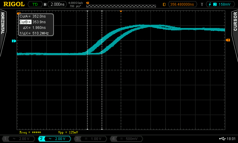
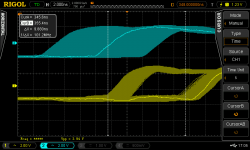
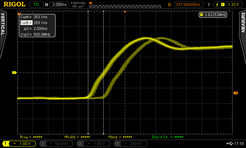
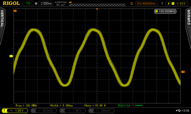
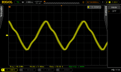
- Looking at the BCK signal first, one can see in the picture below that its edges are alternating to some degree (yellow signal is after the reclocker, blue is before, trigger is set to yellow signal).
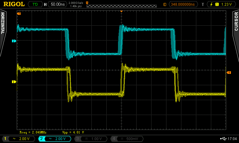
- A closeup shows that the jitter is quite exactly 10ns, which means that the signal shifts via the FF for one cycle of the 100Mhz signal from time to time.

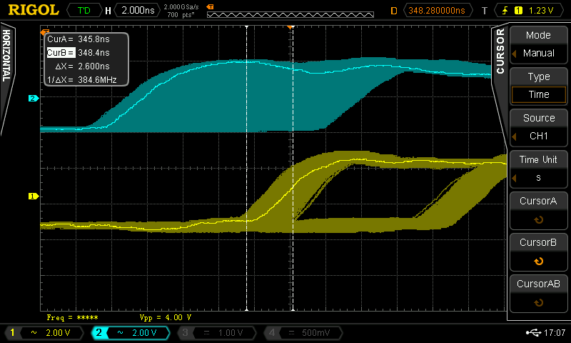
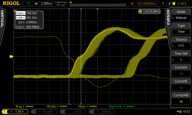
- Interestingly, another cursor measurement shows that besides to the 10ns alternating rising edge, the output signal has a jitter of approx. 2.6ns, which is a surprise to me as the 100MHz signal at the input of the FF seems very clean to me.
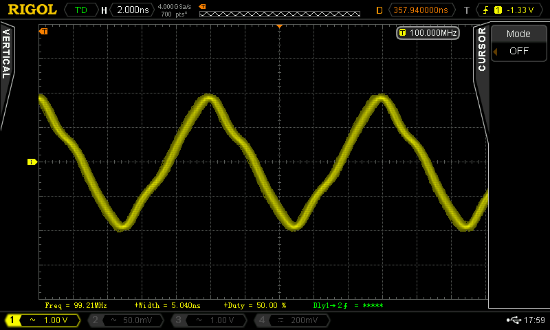
- The 192khz signal looks very jittered as well as can be seen here:
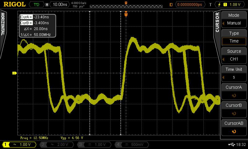
Next I checked the I2S signal right at the Raspberry Pi and found that the edges also alternate to some degree, however, the jitter is only at approx. 2ns - maybe this is due to the clock generation of the I2S signal via the RPi's internal clock? Nevertheless the jitter looks far better than after the reclocker.
What I wonder is the following:
- Am I doing something wrong? Maybe my build of the Acko reclocker is somehow flawed? Or maybe I have an error in my measurement setup?
- Or: Is this the intended behaviour of the Acko reclocker? But - if yes, would the reclocker not add jitter instead of remove it?
For the sound, I personally can't tell the difference between the isolator and the reclocker, but I don't have a lot of listening experience, so it may well be that I miss something here.
Any feedback is appreciated!
Best Regards,
Hermann
I yesterday finished the Acko S03 reclocker for my 4-deck DDDAC, so my chain is now "RPi -> Acko S03 Reclocker with Crystal of 100Mhz -> 4 Deck DDDAC". The reclocker replaces my simpler DIYINKH isolator.
What I was interested in was if and how the jitter would improve, so I checked the I2S signals with my DSO and would like to share my findings / thoughts:
- Looking at the BCK signal first, one can see in the picture below that its edges are alternating to some degree (yellow signal is after the reclocker, blue is before, trigger is set to yellow signal).
- A closeup shows that the jitter is quite exactly 10ns, which means that the signal shifts via the FF for one cycle of the 100Mhz signal from time to time.
- Interestingly, another cursor measurement shows that besides to the 10ns alternating rising edge, the output signal has a jitter of approx. 2.6ns, which is a surprise to me as the 100MHz signal at the input of the FF seems very clean to me.
- The 192khz signal looks very jittered as well as can be seen here:
Next I checked the I2S signal right at the Raspberry Pi and found that the edges also alternate to some degree, however, the jitter is only at approx. 2ns - maybe this is due to the clock generation of the I2S signal via the RPi's internal clock? Nevertheless the jitter looks far better than after the reclocker.
What I wonder is the following:
- Am I doing something wrong? Maybe my build of the Acko reclocker is somehow flawed? Or maybe I have an error in my measurement setup?
- Or: Is this the intended behaviour of the Acko reclocker? But - if yes, would the reclocker not add jitter instead of remove it?
For the sound, I personally can't tell the difference between the isolator and the reclocker, but I don't have a lot of listening experience, so it may well be that I miss something here.
Any feedback is appreciated!
Best Regards,
Hermann
Attachments


Could it be that you have a 100MHz clock which is not a native frequency of either 44.1 or 48 families? While the Pi does generate the clock it has one that is closer to audio samplinsampling frequencies.
just a thought.
Laters,
Drew.
just a thought.
Laters,
Drew.
Hi Hermann,
Thanks for sharing your findings.
I wonder with these experiments, what power supply were you using to power S03? And the configuration as S03 has 3 x 5V inputs.
My experience indicated darker background, noticeable better clarity and focus with S03. Those however were base on ears not scientific measurements!
Cheers.
Hi,
I yesterday finished the Acko S03 reclocker for my 4-deck DDDAC, so my chain is now "RPi -> Acko S03 Reclocker with Crystal of 100Mhz -> 4 Deck DDDAC". The reclocker replaces my simpler DIYINKH isolator.
.....
- Am I doing something wrong? Maybe my build of the Acko reclocker is somehow flawed? Or maybe I have an error in my measurement setup?
- Or: Is this the intended behaviour of the Acko reclocker? But - if yes, would the reclocker not add jitter instead of remove it?
For the sound, I personally can't tell the difference between the isolator and the reclocker, but I don't have a lot of listening experience, so it may well be that I miss something here.
Any feedback is appreciated!
Best Regards,
Hermann
This is the effect of Asynchronous re-clocking and this is a known limitation. I have explained this -> here when Palmito tested his RPi setup this way. I have loosely coined the term 'Pulse-Modulation Errors" and it becomes smaller as the clock frequency is increased. Initially Palmito tested with 50MHz Clock and reported sound is a little bright and sibilate. With 100 MHz Clock it becomes better but errors are still there as you can now see on the scope. So taking it beyond 100MHz could improve things further, of course, assuming your clock jitter is also favourable.
With BBB or similar transports, we get Synchronous Re-clocking and with none of the above issues. It will be interesting to see if actual measurements match what is shown in the timing diagram ->here.
The other benefit is you do not need to spin the Clock too high. So wherever possible go for Synchronous Re-Clocking!
Last edited:
Slow means Fs 22/24.xx going into a device configured for 45/49.xx
Connect as shown to get the right speed:
Acko,
I did what was instructed. When play the music, it is very noisy. It sounds like a pink noise, though I still can hear the music but at very low level. It is like a radio is out of tune. Can you please advise?
Chanh
If I have s03 with 100mhz clock and rPi and wanted to swap to bbb and synchronous clocking instead, will I need different oscillators on the s03?
Also, I'm on the list for a DDDAC-UFL. Am I too late to add a bbb board too?
Thanks,
James
Also, I'm on the list for a DDDAC-UFL. Am I too late to add a bbb board too?
Thanks,
James
Hey James,
I think you will need different oscillator pair yes. Do you have the green or black S03?
Laters,
Drew.
I think you will need different oscillator pair yes. Do you have the green or black S03?
Laters,
Drew.
That makes sense. I have the green s03Hey James,
I think you will need different oscillator pair yes. Do you have the green or black S03?
Laters,
Drew.
James,
From memory that one requires a daughter boards to mount the clocks on, perhaps ask acko what he can do for you? I have a black one that has 90/98 on it, he has it set up so it can be divided down as required.
That would be easiest I reckon.
Laters,
Drew.
From memory that one requires a daughter boards to mount the clocks on, perhaps ask acko what he can do for you? I have a black one that has 90/98 on it, he has it set up so it can be divided down as required.
That would be easiest I reckon.
Laters,
Drew.
RPi & Asynchronous Reclocking - Thougts
Hi,
Thanks to everyone for your feedback, first some answers to your questions / some more details:
Chanh: I'm using the DIYINKH 3,3/5V power supply with a toroid transformer, bzw. here are some pics of my build:
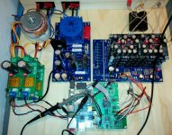
1) The whole DDDAC build (btw., sounding excellent!) with the DIYINKH supply on the left, one set to 3.3V, the other to 5V for the clock generation / Buffer circuit. The lower DIYINKH is for supplying power to the RPi only.

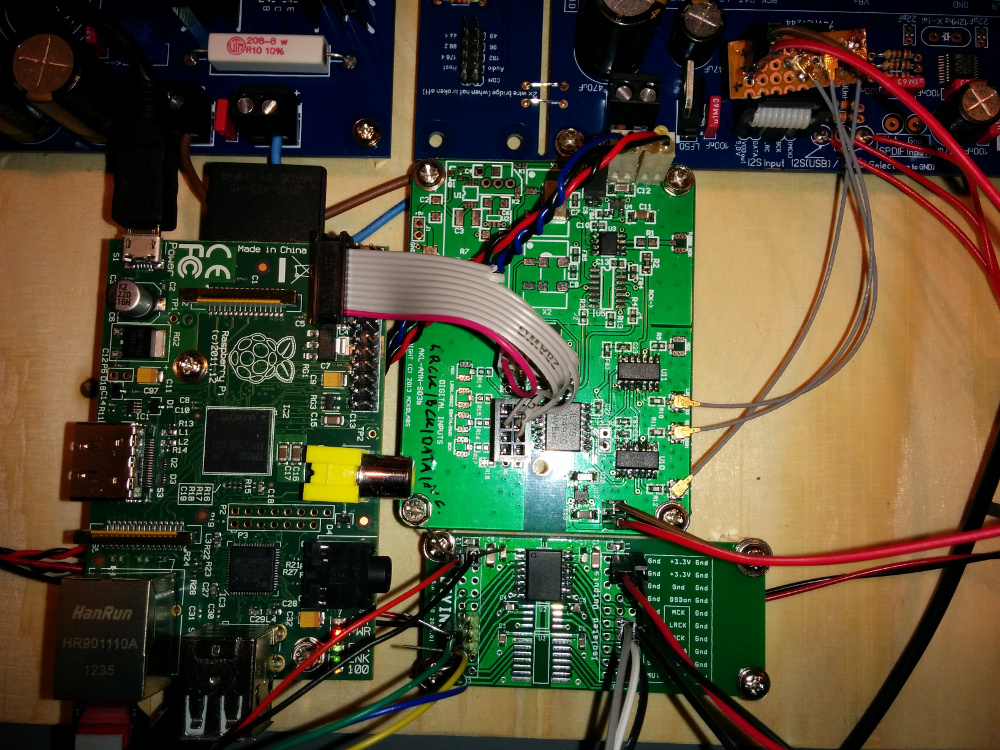
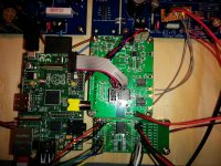
2) The RPi connection, the S03 reclocker along with the DIYINKH isolator:
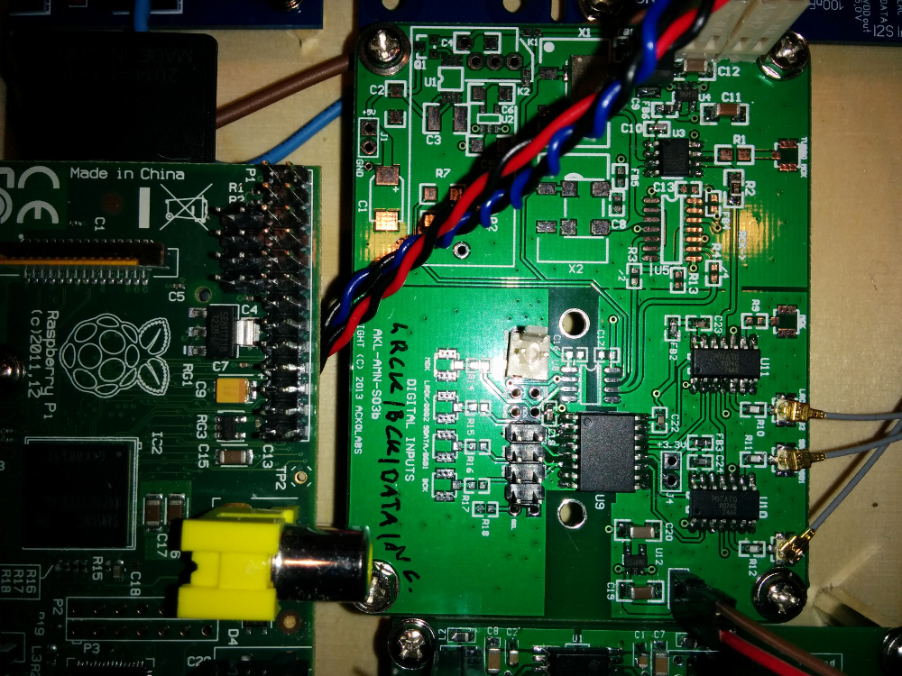
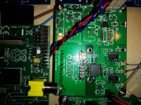
3) And here's a closeup of the reclocker - however, not connected (Btw., for the 100MHz clock, I used the CCHD-575-50-100.000):
Acko: Thanks for input, that's what I somehow suspected - that the 10ns jitter is a result of the asynchronous reclocking. Btw., there's a helpful document regarding the I2S clock generation of the RPi (maybe you know it already):
https://hifiduino.wordpress.com/2014/11/13/raspberry-pi-b-digital-audio/
I did some more measurements that confirm the above link, e.g. one can easily see the 2ns jitter here which comes from the clock alteration of the 500Mhz PLLD:
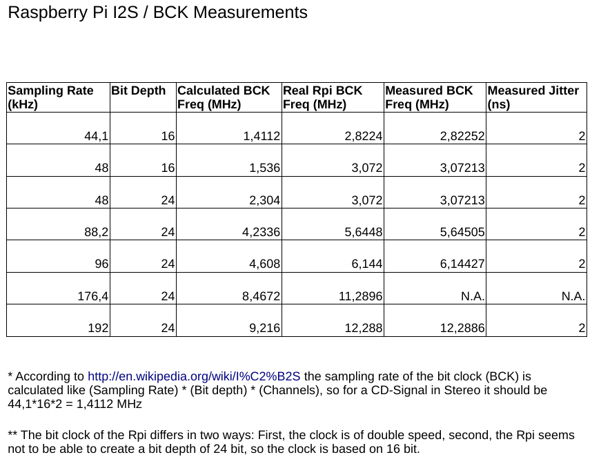
I moreover did some more measurements of the I2S clock frequencies of the RPi which I summed up here:
I'd draw the following conclusions out of this:
So maybe choosing another clock would optimize things for a 44.1/16 setup?
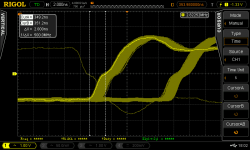
Another thing that I don't understand, however, is the relatively high jitter (~ 2,5ns) at the output of the D-FF:
A look at the 100MHz input of the D-FF shows that the signal is clean but not rectangular, which maybe could be an explanation to the jitter?
It's interesting that the signal before the buffer right at the quartz looks quite similar, maybe even cleaner:
Should not the buffer make the 100MHz signal rectangular? Maybe my buffer is broken in some way? (I accidentally swapped the 5V and 3.3V lines for some seconds - maybe the buffer blew up and now does not rectify the signal but just passes it through?)
Any feedback is welcome!
Best Regards,
Hermann
Hi,
Thanks to everyone for your feedback, first some answers to your questions / some more details:
Chanh: I'm using the DIYINKH 3,3/5V power supply with a toroid transformer, bzw. here are some pics of my build:
1) The whole DDDAC build (btw., sounding excellent!) with the DIYINKH supply on the left, one set to 3.3V, the other to 5V for the clock generation / Buffer circuit. The lower DIYINKH is for supplying power to the RPi only.
2) The RPi connection, the S03 reclocker along with the DIYINKH isolator:
3) And here's a closeup of the reclocker - however, not connected (Btw., for the 100MHz clock, I used the CCHD-575-50-100.000):
Acko: Thanks for input, that's what I somehow suspected - that the 10ns jitter is a result of the asynchronous reclocking. Btw., there's a helpful document regarding the I2S clock generation of the RPi (maybe you know it already):
https://hifiduino.wordpress.com/2014/11/13/raspberry-pi-b-digital-audio/
I did some more measurements that confirm the above link, e.g. one can easily see the 2ns jitter here which comes from the clock alteration of the 500Mhz PLLD:
I moreover did some more measurements of the I2S clock frequencies of the RPi which I summed up here:
I'd draw the following conclusions out of this:
- The BCK is for some unknown reason doubled?
- The RPi can't do 24bit (which is a pity)
- Most of my music material is 44.1/16, so my idea is to concentrate on this format.
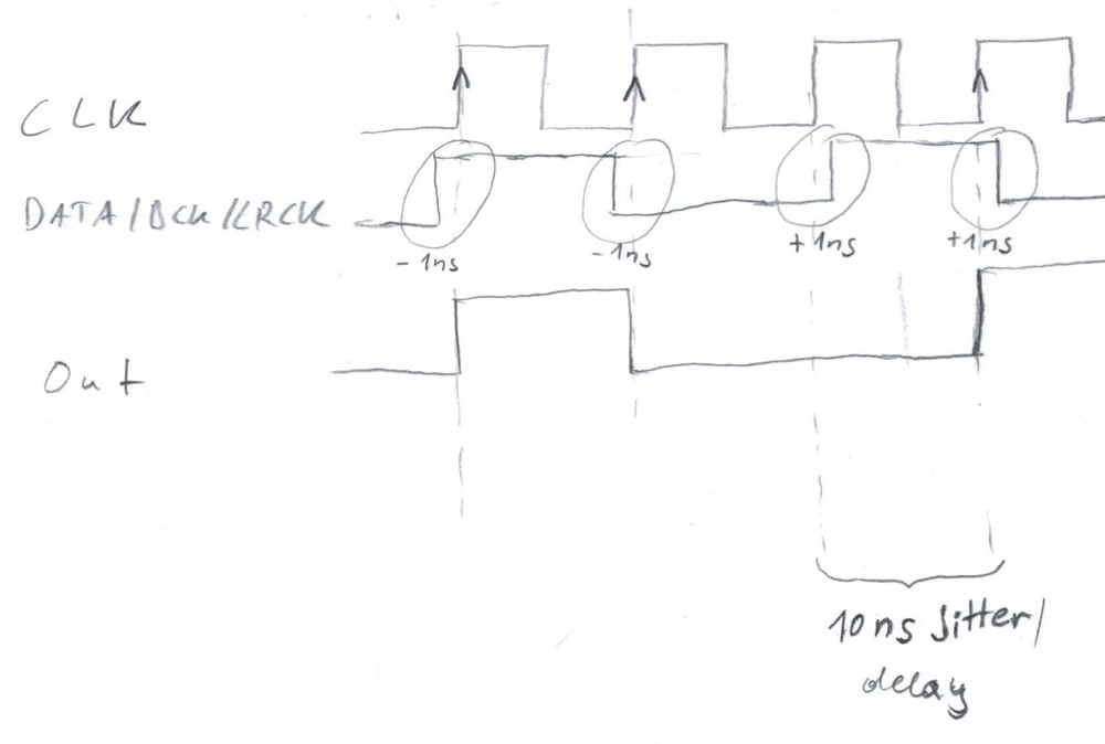
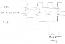
- If I use a clock with a speed of around 100MHz which is a multiple of the 44.1 BCK clock of 2.8224MHz, e.g. 112.896 (if such a clock exists), the issue should improve whereas other signals of a multiple of 48kHz are still heavily affected by the 10ns jitter.
- However, there's a slight probability that the 10ns jitter still occurs - in case the BCK and clock are aligned within the jitter of 2ns, but this should only occur at a probability of 2.8224/112.896) = 2,5%. I tried to depict this in the following sketch:
So maybe choosing another clock would optimize things for a 44.1/16 setup?
Another thing that I don't understand, however, is the relatively high jitter (~ 2,5ns) at the output of the D-FF:
A look at the 100MHz input of the D-FF shows that the signal is clean but not rectangular, which maybe could be an explanation to the jitter?
It's interesting that the signal before the buffer right at the quartz looks quite similar, maybe even cleaner:
Should not the buffer make the 100MHz signal rectangular? Maybe my buffer is broken in some way? (I accidentally swapped the 5V and 3.3V lines for some seconds - maybe the buffer blew up and now does not rectify the signal but just passes it through?)
Any feedback is welcome!
Best Regards,
Hermann
Attachments
-
 S03-Reclock-100Mhz-after-buffer.png38.6 KB · Views: 747
 -
 S03-Reclock-ff-jitter-2ns.png28.8 KB · Views: 586
 -
 sketch-alignment-jitter.jpg43.1 KB · Views: 583
 -
 RPi-I2S-clocks.png92.8 KB · Views: 601
 -
 DDDAC-jitter-I2S-RPI-2ns.png31.8 KB · Views: 605
 -
 DDDAC-reclocker-closeup.jpg423.5 KB · Views: 627
 -
 DDDAC-isolator-reclocker-setup.jpg421.3 KB · Views: 628
 -
 DDDAC-141231.jpg483.4 KB · Views: 614
 -
 S03-Reclock-Quarz-signal.png38.2 KB · Views: 731
Nice work Hermann 🙂
Because the oscillator is only driving the flipfops in this configuration and you're not using mck output from the S03, the buffer isn't really needed I don't think? Maybe you can try the same with disconnecting the power for the buffer chip and bridging the input pin to output pin so the oscillator directly drives the flipflops and see if anything is different?
I have my S03 with DDDAC set up like this and it works fine. I figure less complication is always a good thing, but I'd be interested to see whether you can measure any difference between using the buffer and going direct from oscillator to flipfops.
regards,
James
Ok so for connecting bbb to dddac i would need s03, supercape, dddac ufl?
Is the bbb ufl needed if i use supercape?
Tnx!
Is the bbb ufl needed if i use supercape?
Tnx!
James,
From memory that one requires a daughter boards to mount the clocks on, perhaps ask acko what he can do for you? I have a black one that has 90/98 on it, he has it set up so it can be divided down as required.
That would be easiest I reckon.
Laters,
Drew.
The earlier green S03's only require a daughterboard for the tiny NDK clocks that Acko has sourced for 90/98. Clocks in the two larger sizes typically seen (like the Fox Xpresso and the Crystek 957) will fit without any issue on the green S03.
Greg in Mississippi <---who has both versions of the S03 here slowly making their way into gear!
- Home
- Group Buys
- Amanero Isolator/Reclocker GB