If you check through Ian's FIFO thread he had the same idea and designed the clock boards with little ears that could be cut off and attached using o-rings.I am thinking more along the lines of an "acoustic suspension"
http://www.diyaudio.com/forums/atta...ltimate-weapon-fight-jitter-batteryfromj5.jpg
http://www.diyaudio.com/forums/atta...ct-ultimate-weapon-fight-jitter-si570_top.jpg
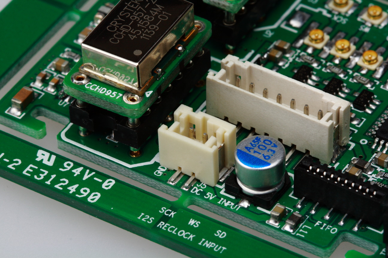
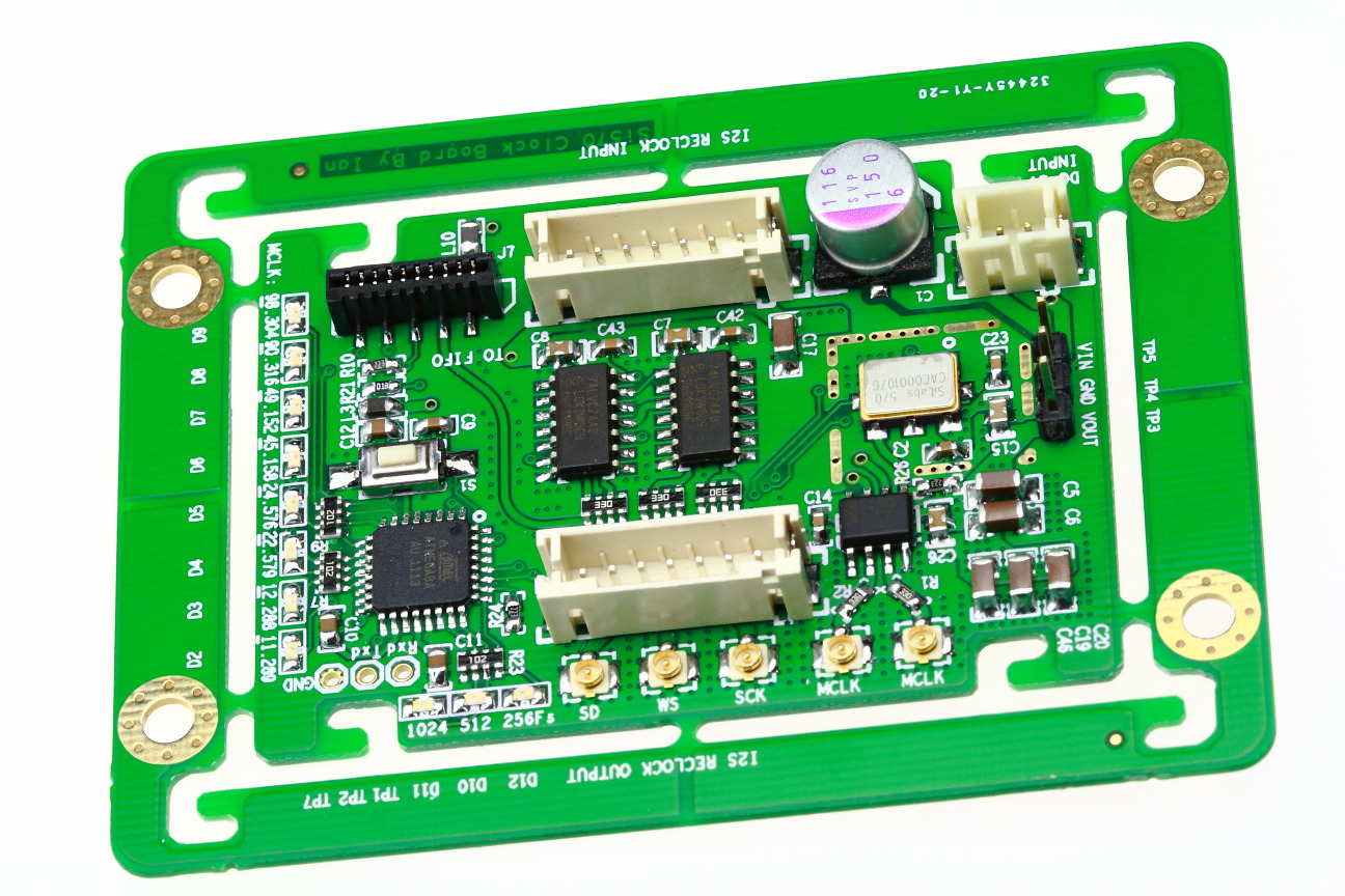
The little tabs joining the inside clock board to the outside pcb frame can be cut and o-rings used to suspend the clock board.
http://www.diyaudio.com/forums/atta...eapon-fight-jitter-frequencyindicatorleds.jpg
But later on he recommended this:
http://www.diyaudio.com/forums/digi...mate-weapon-fight-jitter-343.html#post4074975
Hi Acko,Guys, you cannot use negative supplies (as a second separate supply for S03) unless it is totally floating and isolated. Will damage the S03 !!!
As far as I can see the SSR03 is a bipolar supply with common gnd and not dual floating type. You will have to get another SSR03 to get dual positive supplies of this type.
If you are experimenting with external power supplies consider the following:
1. There may be of little benefit using premium supplies for the digital side as the on-board LDO performance is quite sufficient.
2. Clock power (J1-5V Input) will benefit from high PSSR supplies.
3. You may try external 3.3V clock power direct on J2. But don't forget to remove links K1 and K2 first before connecting external supplies on J2
So I would suggest using premium supplies for clock and regular ones for the digital side.
I notice S03 will benefit greatly with highend audio grade powersupply! Currently, I have SSR03 supplying two +5V digital inputs via its +ve raill, negative rail seems redundantly wasteD! The +5V on the clock input is powering by 5V TentLab Shunt via DDDAC motherboard's i2s input. May try second SSR03 to power the S03 clock input tomorrow?
An externally hosted image should be here but it was not working when we last tested it.
Regards,
Chanh
Last edited:
Hi Acko,Hi Acko,
.....grateful for the refund.....
Have recieved my refund today!

Cheers again, look forward to your SuperCape and other future upgrades! 🙂
Chanh
If you check through
Thanks, (I know). I might knock up a little frame like that for the S03. 🙂
Hi Acko,
I notice S03 will benefit greatly with highend audio grade powersupply! Currently, I have SSR03 supplying two +5V digital inputs via its +ve raill, negative rail seems redundantly wasteD! The +5V on the clock input is powering by 5V TentLab Shunt via DDDAC motherboard's i2s input. May try second SSR03 to power the S03 clock input tomorrow?

Regards,
Chanh
Hi Chanh,
The clock benefits if you place the shunt regulator directly next to the clock. The wires running from the dac board to the clock have a fairly large impedance in view of the high frequency that the clock is running ( and thus drawing current influenced by this frequency).
I have the black board with extra holes for a regulator for the clock, I assume there will be some way to place it near the clock on the older board.
Regards,
I have an older green board but I only noticed recently when you mentioned it that I also had the 3 mounting holes for a standard 3 legged reg. So I was able to change from this mess (you can see the 3 holes at the bottom of this pic)I have the black board with extra holes for a regulator for the clock, I assume there will be some way to place it near the clock on the older board.
Regards,
An externally hosted image should be here but it was not working when we last tested it.
To this. Much neater 🙂
An externally hosted image should be here but it was not working when we last tested it.
There's a place on the underneath of the board which needs a solder jumper if you want to use this point. It's obvious if you look.
If you check through Ian's FIFO thread he had the same idea
But later on he recommended this:
http://www.diyaudio.com/forums/digi...mate-weapon-fight-jitter-343.html#post4074975
Ahh cool. Those bushings are easy to get hold of and not expensive 🙂
http://pages.ebay.com/link/?nav=item.view&id=400761335254
Thanks Stefan! Great to read you & James back on board!The clock benefits if you place the shunt regulator directly next to the clock. The wires running from the dac board to the clock have a fairly large impedance in view of the high frequency that the clock is running ( and thus drawing current influenced by this frequency).
Would you share your ideal powersupply for this clock and may be BBB too? Currently, I still using the 5V USB battery to power BBB, those use to charge iPhone.😀
I was thinking of shorten the length path between shunt and S03 but concerning of EMF as S03 is being too close to DDDAC? Would you say, best to use a seperate ps and not from DDDAC on board Shunt? Apparently, SSR03 can have dual +ve rails, but share common ground plane. Not sure if there is any benefit in doing so in term of isolation? Otherwise, I might tweak this SSR03 to have dual positive rails output, so one uses to power the clock and the other to power the remain digital +5V.I have the black board with extra holes for a regulator for the clock, I assume there will be some way to place it near the clock on the older board.
Realise I have too many questions! 🙂
Many thanks,
Chanh
Brian,
Thank you for your email.
I do indeed very much appreciate and accept your sincere apology.
I would like nothing better than to forget the whole incident and move forward.
All the best!
Last edited:
Brian,
Thank you for your email.
I do indeed very much appreciate and accept your sincere apology.
I would like nothing better than to forget the whole incident and move forward.
All the best!
Well done guys, love and peace at Christmas time.

Ahh cool. Those bushings are easy to get hold of and not expensive 🙂
http://pages.ebay.com/link/?nav=item.view&id=400761335254
It would be cool to print some nice dampeners with my new toy: ultimaker 😀
Any ideas on a nice design?
Regards,
Thanks Stefan! Great to read you & James back on board!
Would you share your ideal powersupply for this clock and may be BBB too? Currently, I still using the 5V USB battery to power BBB, those use to charge iPhone.😀
I was thinking of shorten the length path between shunt and S03 but concerning of EMF as S03 is being too close to DDDAC? Would you say, best to use a seperate ps and not from DDDAC on board Shunt? Apparently, SSR03 can have dual +ve rails, but share common ground plane. Not sure if there is any benefit in doing so in term of isolation? Otherwise, I might tweak this SSR03 to have dual positive rails output, so one uses to power the clock and the other to power the remain digital +5V.
Realise I have too many questions! 🙂
Many thanks,
Chanh
Hi Chanh,
It's a bit too early to answer your question on the ideal supply for the S03, I hope to finish the S03 board the next weeks.
I will use a shunt regulator positioned next to the clock, I have good experience with this in CD player designs I made in the past. The raw power does not need to be regulated, but I will try what I have laying around for now; a supply with simple LM317 but with some nice black gates, and take it from there. The clock benefits most from a very fast and close (very close is important! Best to solder directly to the power leg of the clock, more than a few cm apart does have negative influence) to the clock positioned regulator. Do not use big caps (max about 0,1uF) between the regulator and the clock, this will slow down current supply.
I am using the salas shunt regulator for the raspberry pi now. I have not noticed big changes with other supplies, as long as they are linear.
Regards,
Last edited:
An externally hosted image should be here but it was not working when we last tested it.
so my 50mm ufl leads turned up today 🙂 
What's the schedule on the ufl/dddac boards please Acko?
I have a AKL-AMN-S03 board that looks a bit different to the one pictured, is it still good to do the BBB setup with the Supercape once its ready or do I need the latest S03?
The previous boards are good to go!
The new board (black) has the land pattern to mount the tiny NDK crystals as well but other than that they are pretty much the same. If you wish to use the NDK ones, there are adapter boards (CCHD950 size) available to suit.
What's the schedule on the ufl/dddac boards please Acko?
Great stuff!
Boards for use with S03 are all on order, expecting in ~2wks:
1. DDDAC-UFL (revised to correct board error)
2. BIII-UFL (2CH)
3. BBB-UFL
3. NDK2520-CCHD950
Will contact those who are on the list as soon as they become available:
Giulio: BBB - UFL (1x) + BIII - UFL (1x) both with UFL mounted
IanS1: DDDAC-UFL (with UFL mounted) X2
Myint67 DDDAC -UFL (with Ufl mounted )x2
Stijn001: DDDAC-UFL (with Uf.L.'s mounted) 2x
Dwjames: DDDAC-UFL (with Uf.L.'s mounted) 1x
Last edited:
Excellent, thanks 🙂Great stuff!
Boards for use with S03 are all on order, expecting in ~2wks:
Hi Acko, Just to make sure. I saw the board you made for Chan had two clocks installed but R18 in place. However elsewhere it was suggested that R18 was only to be used in case of a single clock X1. Can you elaborate on this? I’m planning to use two clocks 45/49Mhz in combination with the BBB.
Hi Acko, Just to make sure. I saw the board you made for Chan had two clocks installed but R18 in place. However elsewhere it was suggested that R18 was only to be used in case of a single clock X1. Can you elaborate on this? I’m planning to use two clocks 45/49Mhz in combination with the BBB.
R18 is effectively a pull down resistor if you look at the schema. It is to ensure that only one of the clocks is selected (active) in case the inputs get/are disconnected. Of course in a connected system the preceding logic ensures correct operation by setting the CKSEL to high or low. So, yes, in case of Chanh's build R18 is not really needed because of the CKSEL drive from BBB but no harm leaving it there plus safety reasons -default factory build
Re: default factory build with Dual Clocks
In case of input disconnection or if CKSEL is not available or not used e.g single clock operation for Async then you are assured that the presence of R18 sets logic correctly. If R18 is not present then CKSEL floats when input is disconnected and you get the possibility of both on-board clocks becoming active causing unnecessary switching!
Last edited:
Your setup is fine w.rt. EMI from BBB.
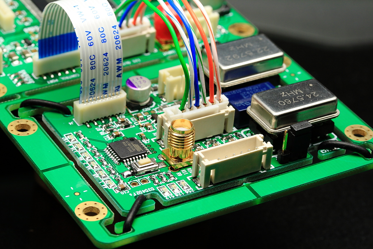
I am thinking more along the lines of an "acoustic suspension" as shown, given there is a sensitive clock on board as explained in my previous post. So will prefer a horizontal setup and connection using flexi cables will put the S03 Clock into the 'swing of things' 🙂
I have no expertise in these matters and I'm not suggesting that 'rubber bands' or the like wont make a difference but, at the frequency that clock crystals operate at won't the suspension essentially act as a solid/rigid connection? Can anyone contribute to my education?
Ray
- Home
- Group Buys
- Amanero Isolator/Reclocker GB