jnb said:
I don't know but my guess, for FWIW, is that Johan Potgieter might say it is being capacitively coupled into the signal path somehow.
I see. I was wondering about filament induced hum, or mains transformer eddy currents voltage between two points in the chassis. But, yes, many times capacitive coupled hum could be underestimated... And this could be some degrees out of fase of the power line, which can be only in fase or 180 degrees out of fase, perhaps...
Yes, that seems reasonable. In my case I have so little noise on my heaters I cannot reliably measure it.
Your idea of chassis current made me think that the signal shields can capacitively couple to the chassis, and the internal conductors can couple to the shields.
Furthermore, the hum is reduced - slightly when I touch the chassis, and significantly when I touch the chassis near the phono stage sockets.
jnb said:Yes, that seems reasonable. In my case I have so little noise on my heaters I cannot reliably measure it.
Your idea of chassis current made me think that the signal shields can capacitively couple to the chassis, and the internal conductors can couple to the shields.
Furthermore, the hum is reduced - slightly when I touch the chassis, and significantly when I touch the chassis near the phono stage sockets.
G'day, jnb.
Are you shure you connected the chassis to a good ground? And, is there any ground loop in the connectors to the turntable? Are the phono connectors insulated from the chassis and the common connection of them connected to a single point nearest to the first valve of the phono stage? And, what about the turntable ground? For shure you know, but's just a hint...
Cheers.
Larry.
I have been able to bring the noise down substantially by switching to a buss type ground but it is still sensitive to touching the chassis or volume pot. I am averaging 20mVp-p of 50Hz. The CD input only shows 1mV at the output). My pre (which is unusual in that it is designed for connection to a unity gain buffer), has over 70dB of gain from the phono input so these may be small currents, however, I don't know whether the phono stage is involved in amplifying the noise. The other stage gain is just 26dB.
The thing that worried me is that the noise level is not stable and changes with location, time, and what I do around it on the bench (besides moving a cordless mouse 🙄 ).
The worst thing that happened is that the amp would oscillate when the volume control was at either extreme, or would drop out. The volume control is at the end of the amp not the beginning. I seem to have put this at bay by relocating the pot grounds to a different part of the buss. I'm not sure I fixed it per se, I may just have reduced the oscillator stimulus feedback.
I have made only minimal improvements by optimising the order of ground connections as best I can.
My amp circuitry is DC isolated from the chassis/safety ground except for one point at the phono input, the RCAs are isolated and I am doing my testing with the inputs shorted. My volume pot body is internally isolated from the pot grounds.
jnb said:I have been able to bring the noise down substantially by switching to a buss type ground but it is still sensitive to touching the chassis or volume pot. I am averaging 20mVp-p of 50Hz. The CD input only shows 1mV at the output). My pre (which is unusual in that it is designed for connection to a unity gain buffer), has over 70dB of gain from the phono input so these may be small currents, however, I don't know whether the phono stage is involved in amplifying the noise. The other stage gain is just 26dB.
The thing that worried me is that the noise level is not stable and changes with location, time, and what I do around it on the bench (besides moving a cordless mouse 🙄 ).
The worst thing that happened is that the amp would oscillate when the volume control was at either extreme, or would drop out. The volume control is at the end of the amp not the beginning. I seem to have put this at bay by relocating the pot grounds to a different part of the buss. I'm not sure I fixed it per se, I may just have reduced the oscillator stimulus feedback.
I have made only minimal improvements by optimising the order of ground connections as best I can.
My amp circuitry is DC isolated from the chassis/safety ground except for one point at the phono input, the RCAs are isolated and I am doing my testing with the inputs shorted. My volume pot body is internally isolated from the pot grounds.
G'day, jnb,
Sorry for missing. I think we better start a new thread where other people can help, I think your problems don't relate too much with a chassis material rather than with some kind of self oscillations at RF. You can have a very bad circuit, with any kind of hum and buzz, and a lot of funny troubles but definitely this seems to me an RF oscillation problem.
Do you own an oscilloscope? If you do, go in search for oscillations.
Cheers
Larry.
I have a large piece of block aluminum that was used to align the wheels on a Formula 1 race car. It is 8" x 26" x 1" thick, I picked it up off the concrete and it rang like a bell for about 20 seconds......I was shocked as I thought my hand would deaden the ringing. I suspect all metals would ring on a small scale which could effect all individual components. Similar to a capacitor inside a speaker box.
Not to mention micro phonics of valves hard connected to a chassis plate.
Something to think about during construction.
Ron
Not to mention micro phonics of valves hard connected to a chassis plate.
Something to think about during construction.
Ron
I read through the entire thread. It was generally agreed that an aluminium chassis is easy to work with. It sounds better than a steel chassis but no detailed reasoning was given.
I think this youtube video shows us the reason - steel affects transformers' magnetic field while aluminium does not:
https://www.youtube.com/watch?v=Ifg1JUgByFc
I use aluminium chassises but they all sit on a HiFi rack built from solid steel sheets so the effect is similar to having steel chassises.
I wonder if toroidal transformers are located 2 inches away from the steel sheets would it still matter? 😕
It makes the sound coming out of speakers better?I read through the entire thread. It was generally agreed that an aluminium chassis is easy to work with. It sounds better than a steel chassis but no detailed reasoning was given.
Back in the day when all electronic equipment had valves (tubes) they usually had a steel chassis. I guess that was to do with the economics of mass production, but I do remember that the amateur builders usually used aluminium (aluminum), and that was because it was easier to cut and shape than steel. There was lively debate as to which material was 'best' and there was an article in some magazine that analysed the problem. As far as I remember the arguments were: - aluminium has a lower resistance than steel so can be better for earthing(grounding), - steel is magnetic which means that it is not so good for radio frequency use because of the skin effect. (A cure is to tin or copper plate the steel, but not nickel plate - nickel is also magnetic), - transformers have stray magnetic fields which, (for transformers handling high power), can exert a mechanical force on steel but not aluminium, - transformer iron cores exhibit magnetostriction so transformers with high power going through them can be audible - this mechanical force can be transferred to both steel and aluminium but in general steel is much stiffer than aluminium and may make a better sounding board, - steel does provide better shielding at low frequencies (eg audio) because it is a reasonable conductor and is reasonably magnetic (MuMetal was the thing then). Transformers have improved immensely since then but I would guess that it is still a good idea to include some form of magnetic shielding and some form of mechanical isolation for higher power items.
I think a steel chassis affects the transformer performance and the transfromer induces currents in the steel chassis. The amplifier ground must be connected to the chassis so ripples are induced into the signal in that way. With aluminimum, this effect is much smaller.
You can get,
Transformer coupling with a steel chassis. I like aluminium and wood..😀
You can Anodise aluminium after its cut, however remember that the anodising insulates the aluminium so you have to grind back where earthed connections are made so plan well so they are hidden from the outside.
Why do I like the purple PYE logo so much..🙄 (Oups sorry I digress) 😀
Steel is more difficult to work with and if the paint chips it rusts.. Stainless is nice but copper is interesting..but is has to have wood... birds eye maple....LOL 😀
http://audio-heritage.jp/UNISONRESEARCH/amp/845absolute.jpg
Regards
M. Gregg
Last edited:
Even that steel is being magnatised bij the power transformer i alway use galvanized steel
So you can solder the wires directly on the chassis.
So you can solder the wires directly on the chassis.
Even that steel is being magnatised bij the power transformer i alway use galvanized steel
So you can solder the wires directly on the chassis.
I use wood with double sided PCB inside the top plate and solder to that I have put EMI tape under it in the past..
The problem with coupling means you can get hum from the power Tx coupling to the OP tx's.
Regards
M. Gregg
I use wood with double sided PCB inside the top plate and solder to that I have put EMI tape under it in the past..
The problem with coupling means you can get hum from the power Tx coupling to the OP tx's.
Regards
M. Gregg
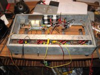
I don't use any PCB's in my amps mostly i hardwire.
I only use small pcb boards in mij power suply and my delay switch when needed.
Attachments
Has anyone any before/after experience of steel transformer covers, for example the Lundahl covers. Housings | Lundahl Transformers They should reduce the influence of stray magnetic fields from transformers.
But not an issue for audio frequency.steel is magnetic which means that it is not so good for radio frequency use because of the skin effect. (A cure is to tin or copper plate the steel, but not nickel plate - nickel is also magnetic),
What is considered "high power" in tube amps?I would guess that it is still a good idea to include some form of magnetic shielding and some form of mechanical isolation for higher power items.
Did it make audible difference? If not, why bother?I think a steel chassis affects the transformer performance and the transfromer induces currents in the steel chassis. The amplifier ground must be connected to the chassis so ripples are induced into the signal in that way. With aluminimum, this effect is much smaller.
I don't use any PCB's in my amps mostly i hardwire.
I only use small pcb boards in mij power suply and my delay switch when needed.
I hard wire as well the PCB is used like this..Not as a PCB..😀
Under the transformers I line the case with EMI tape.
Regards
M. Gregg
Attachments

Last edited:
- Status
- Not open for further replies.
- Home
- Design & Build
- Parts
- Aluminium vs steel chassis