copper & steal
For my dac I used 2.5mm zinc plated steal and the trannies and
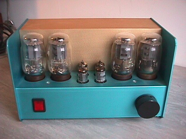
output stages 2mm copper ,rapped the polyprop caps in copper
so I tried to sheild for RF & EMI .the pre is similar both are dead quiet .The top case will be wood .
http://i55.photobucket.com/albums/g158/malcolm_05/diyfi001.jpg
Cheers.
For my dac I used 2.5mm zinc plated steal and the trannies and
output stages 2mm copper ,rapped the polyprop caps in copper
so I tried to sheild for RF & EMI .the pre is similar both are dead quiet .The top case will be wood .
http://i55.photobucket.com/albums/g158/malcolm_05/diyfi001.jpg
Cheers.
Wow thats some clean work, nice! One suggestion though, when you are finishe you can spray clear coat on the copper to keep it from tarnishing.
Nick
Nick
whitelabrat said:I've got a hammond steel chassis myself, but I don't know what tools are needed to punch the holes. It will have hammond transformers three octal and one noval tube sockets.
Or can any recommend where I could have this done in the US?
Whitelabrat you have a few option, there are green lee punches, you can find a local sheet metal fab shop, or you can cut them by drilling holes and conecting the dots with a dremel tool.
Personally I would go find a sheet metal shop it will be cheaper then buying green lee puches It would also be quicker and easier then dremeling it.
Nick
whitelabrat said:Or can any recommend where I could have this done in the US?
Any machine shop could do this easily, but if you are going to continue building amps, you need to invest in a set of hole punches. Buy MADE IN THE USA - my set has been used for 30 years (by my father and now me) and still works like the day they were new. I saw a set at Lowes the other day for something like $330 or so. It's not cheap, but they'll last forever if you take care of them. A few trips to the machine shop will cost you that anyway...
Lowes link
Cycline3 said:
I saw a set at Lowes the other day for something like $330 or so. It's not cheap, but they'll last forever if you take care of them. A few trips to the machine shop will cost you that anyway...
Lowes link
Conduit punches including the referenced set at Lowes are sized to match the outside diameter (o.d.) of US standard sized conduit. For example, a 1/2-inch conduit punch actually cuts a hole 7/8-inch in diameter to match the 7/8-inch o.d. of 1/2-inch conduit.
I use the Greenlee 730 series. Their stated size matches the hole size cut. A couple of examples of the 730 series listed here:
http://www.alliedelec.com/Search/Pr...=&DESC=730-5/8&R=799-3214&sid=46E72C00475E17F
and
http://www.newark.com/jsp/search/browse.jsp?N=1000542&Ntk=gensearch_001&Ntt=greenlee+730&Ntx=
dave
drj759 said:Conduit punches including the referenced set at Lowes are sized to match the outside diameter (o.d.) of US standard sized conduit.
True that. Though I've never measured them or had the need to.. simply, there is one that makes perfect 9 pin holes and one that makes perfect octal socket holes. I'm a happy camper being able to do that. Again, if you are going to keep making amps, I cannot see how you wouldn't want a set of these...
Hello,
This is a real interesting thread... and a pretty good problem too.
Well, It is my point of view, that we need to split it in some other simpler tech problems.
Do we think magnetism is a real concern?
Do we think money is a real concern?
... do
... appearence...
.. mechanics...
... time consuming working...
... soldering...
... eddy currents...
... strenght...
... conductivity...
... vibration...
... statics...
... all of this is a real concern?
Indeed they are so I made an iron 1.6mm thick chassis, just black soft iron... I welded the corners to avoid vibrations and for aspect pourposes, after, I drilled the holes where needed. I cleaned the iron with clorine acid and then plated it with tin/silver. The one used for soldering. The chassis is magnetic, but it is not magnetizable... in the sense it does not retains magnetism, just becouse it is made of mild iron. After that... I got conductivity, strenght, no vibration, no statics, ease of soldering, all the mechanics I'd like, but aspect wasn't so cool...
No way to plate it with chromium or what else...
So, I made a counter plate, for the top of it, of stainless steel 0.8 mm thick sheet. Right, I started again making holes, and stainless is not so easy to work. At last I finish the top mirror like. Everything on top was mounted on teflon fittings, so no eddy currents induced by conduction loops coming from anywhere.
This is not alluminum, this is not light weight, this is not so chip, not so easy to drill, in other words, this is hard working and expensive.
But, it is "funcionally beatifull", I'm satisfied of it, and regardles of all other features, this is the main goal I was looking for.
Am I wrong on this? 🙄
Regards.
What about Copper?? I am about to assemble a 50CA10PP on a 3mm Cu-plate. Guess I have to add some brackets underneath as copper is rather soft.
soundbrigade said:What about Copper?? I am about to assemble a 50CA10PP on a 3mm Cu-plate. Guess I have to add some brackets underneath as copper is rather soft.
Am... un uomo "saggio"... not "soggio"... 😀
Well, copper is a very good material, nice to work, but it have the tendency to turn black after few days. Do not touch it with your fingers becouse the fingerprints turns to strange colours. Somentimes, grenish oxyde appears near weldings or where the copper gets in contact with chemicals. This is one of the reason copper is sometimes silver plated, gold plated or chromium plated as well. Brass is still a good stronger material than copper, less prone to oxydation and it is easily plated with the same metals while it is easy to machine allmost as copper is.
If you paint with clear laquer a copper surface it remains as beatyfull as you polish it for months, but, soon or later, it'll start to blacken. The same is for brass.
Both copper and brass are no magnethic materials so, they don't conduct magnetic fields, but neither screen them out. While both of them are of easy soldering and good conductors.
If the sheet is soft and jerks you can stiffen it with soldered brackets. Better TIG welded.
UHF and SHF amplifiers stages are made of copper or brass silver plated for RF screning pourposes.
Thats all I can say.
Cheers.
I have used 3mm aluminium sheet for the top of my chassis and timber for the rest and have no problem I think layout of components is important as mentioned by others and good grounding. MJ also recommends fiberglass or paxolin board under transformers. And using some reasonable hole saws and plenty of WD40 and finishing with emery cloth its much easier to work with.
Nigel
Nigel
nkg said:I have used 3mm aluminium sheet for the top of my chassis and timber for the rest and have no problem I think layout of components is important as mentioned by others and good grounding. MJ also recommends fiberglass or paxolin board under transformers. And using some reasonable hole saws and plenty of WD40 and finishing with emery cloth its much easier to work with.
Nigel
Yes, I agree. First most important thing is the project, component lay out, then wiring. Component lay out comprises isolation, mechanical fastening, magnethic isolation... I use a 1mm thick teflon gasket between magnethics component and the chassis, each component, either tranny or choke earted in a single point by means of a wire. But anything else from vetronite or other PCB material is good. I find that teflon is a bit softer and fit better than stiffy material. The rest is "glamour" 😀
Anyway, I find that raw alluminun is soft and prone to scratches, unless you can anodize it. But, if you can, well, this can be a very nice strong finish.
Larry Lomax said:I use a 1mm thick teflon gasket between magnethics component and the chassis, each component, either tranny or choke earted in a single point by means of a wire.
I have my power transformers bolted to my aluminium chassis, thinking they need to be earthed. I have been considering the four bolts to be a single point, for all intents and purposes, due to their proximity.
I'm not sure I understand what you're saying here, could you explain it another way please?
G'day jnb...
Indeed they are a single point, but they are also four single points and when there is a flux leak from the tranny, unwanted eddy currents circle throgh the chassis. I use isolation fittings like the ones used by TO3 transistors through the holes and the screws. For safety, I run a wire from samwhere in contact with the tranny to ground, to just one point. So, there could'nt be a closed circuit where induced currents can circulate.
A friend o mine attached to ground a toroidal tranny with a wire by the central screw... the wire sets allways afire... This is the idea... 😀
😱 😀 is it acting as a shorted turn?Larry Lomax said:... the wire sets allways afire... This is the idea... 😀
Thanks Larry Lomax. My biggest problem is 50Hz. I'll get some insulation for three bolts and make sure the other makes good contact.
Jnb,
If you can get it on a scope, is that 50 Hz interference in phase with the mains, or 90 degrees off?
If you can get it on a scope, is that 50 Hz interference in phase with the mains, or 90 degrees off?
Johan Potgieter said:Jnb,
If you can get it on a scope, is that 50 Hz interference in phase with the mains, or 90 degrees off?
OK, I did that and the mains is 90 degrees off.
jnb said:
😱 😀 is it acting as a shorted turn?
Thanks Larry Lomax. My biggest problem is 50Hz. I'll get some insulation for three bolts and make sure the other makes good contact.
Yup, and he tried again and again, each time with a stronger piece of wire... No way to stop the EM bleading...

I'm interested on the testing hum diagnosys too...

Why the fase shift?
Cheers
Larry.
Larry Lomax said:I'm interested on the testing hum diagnosys too...
Why the fase shift?
Cheers
Larry.
I don't know but my guess, for FWIW, is that Johan Potgieter might say it is being capacitively coupled into the signal path somehow.
- Status
- Not open for further replies.
- Home
- Design & Build
- Parts
- Aluminium vs steel chassis