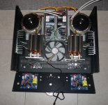
Well, the Modushop cases arrived last week ... so here are the first 2 pics of the build of my first AN 4R. 🙂 SLBs are in place!


I'm using a 3U, 350mm deep SlimLine case (as I don't need heatsinks for the MOSFETs since I'm using a Dell CPU cooler for each pair ... plus a fan).
As per Bfpca's excellent suggestion, I have strengthened the flimsy base of the case with a 2mm steel sheet that I had made up by my metal man.
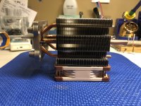
Next is to mount the Dell CPU coolers.
Andy
I'm using a 3U, 350mm deep SlimLine case (as I don't need heatsinks for the MOSFETs since I'm using a Dell CPU cooler for each pair ... plus a fan).
As per Bfpca's excellent suggestion, I have strengthened the flimsy base of the case with a 2mm steel sheet that I had made up by my metal man.
Next is to mount the Dell CPU coolers.
Andy
Last edited:
Looking good Andy!
It’s nice to see all your hard work in a real chassis now 🙂
Cheers,
Vunce
Thanks, V. 🙂
It will be a well-packed chassis when it's all put together! And still a lot of work to go! 😀
Andy

Hello,
I would like to congratulate and thank all of you who have participated in the creation of this fantastic class A amplifier ... and that it be shared in this great audio forum!
Being Alpha Nirvana 39w (27db gain approximately) the best candidate for the next construction, I am looking for a preamp that makes a good match. The weakest source signal I have, comes from the 550mV phono preamp output.
The highest signal is from the CD 2V ~ reader.
In the course of this thread, I seem to have read that the Alpha Nirvana's input sensitivity is 630mVRMS and this makes me doubt the choice of preamp gain to use.
I am thinking of Yarra / Melbourne adjusted to 12dB of gain, it would be fine for the 630mV of the pream phono but I am left over for 2Vout CD player.
Any comment will be welcome .
Thanks and best regards
Something to consider:
- don't calculate with the usual 2 VRMS output of digital sources; 1 VRMS "average" is better as it depends on the recording;
- the gain of your phono preamp is fixed; output level therefore depends on what your cartridge delivers. When it is "550 mV" now, that would mean that the amplifier would reach about 30 watt of output power instead of 39 watt. In terms of the difference in dB SPL when listening to music this is totally irrelevant.
You could try some sort of passive preamp first.
Very neat work, Andy!
HD
Thanks, Hugh. 🙂
The final put-together certainly takes a lotta time! 🙁
And once I've assembled it all so that I can switch it on (having first confirmed the 'right' way round to connect up each power toroid) ... I have to measure the DC offsets on each channel - so I can adjust the Bourns pot inserted into X111 to get zero DC offset (or near enough to this), measure the pot value and then disassemble, in order to solder in the equivalent value res at R113.
Andy
Last edited:
Hi X,
1'd be grateful for your advice in terms of measuring the value of the Bourns pot in X111.
The trim-pot is inserted into X111 with the screw on the RHS (when looking at the PCB so that the input Molex connector is at the top).
I'm not 100% sure which of the 2 connectors you have put onto the same PCB track - so can you please tell me which 2 out of the 3 trim-pot pins I should use to measure the value of the res that is to be used in R113 (when I remove the trim-pot, after zeroing DC offset):
* the middle pin plus the one on the RHS (under the screw)?
* or the middle pin and the one on the LHS?
My guess is that I measure the value between the centre pin and the pin under the screw?
Thanks,
Andy
Last edited:
Something to consider:
- don't calculate with the usual 2 VRMS output of digital sources; 1 VRMS "average" is better as it depends on the recording;
- the gain of your phono preamp is fixed; output level therefore depends on what your cartridge delivers. When it is "550 mV" now, that would mean that the amplifier would reach about 30 watt of output power instead of 39 watt. In terms of the difference in dB SPL when listening to music this is totally irrelevant.
You could try some sort of passive preamp first.
Thanks daanve. You are right with the output level of some recordings in CD format, I had not thought ... I could certainly test its operation before deciding on active preamplifier.
Regards
Last edited:
Hi Andy,
If you look at the schematic you will see that pins 2-3 are tied together. So first take your DMM and check continuity to determine which is which. The silkscreen should show pin 1.
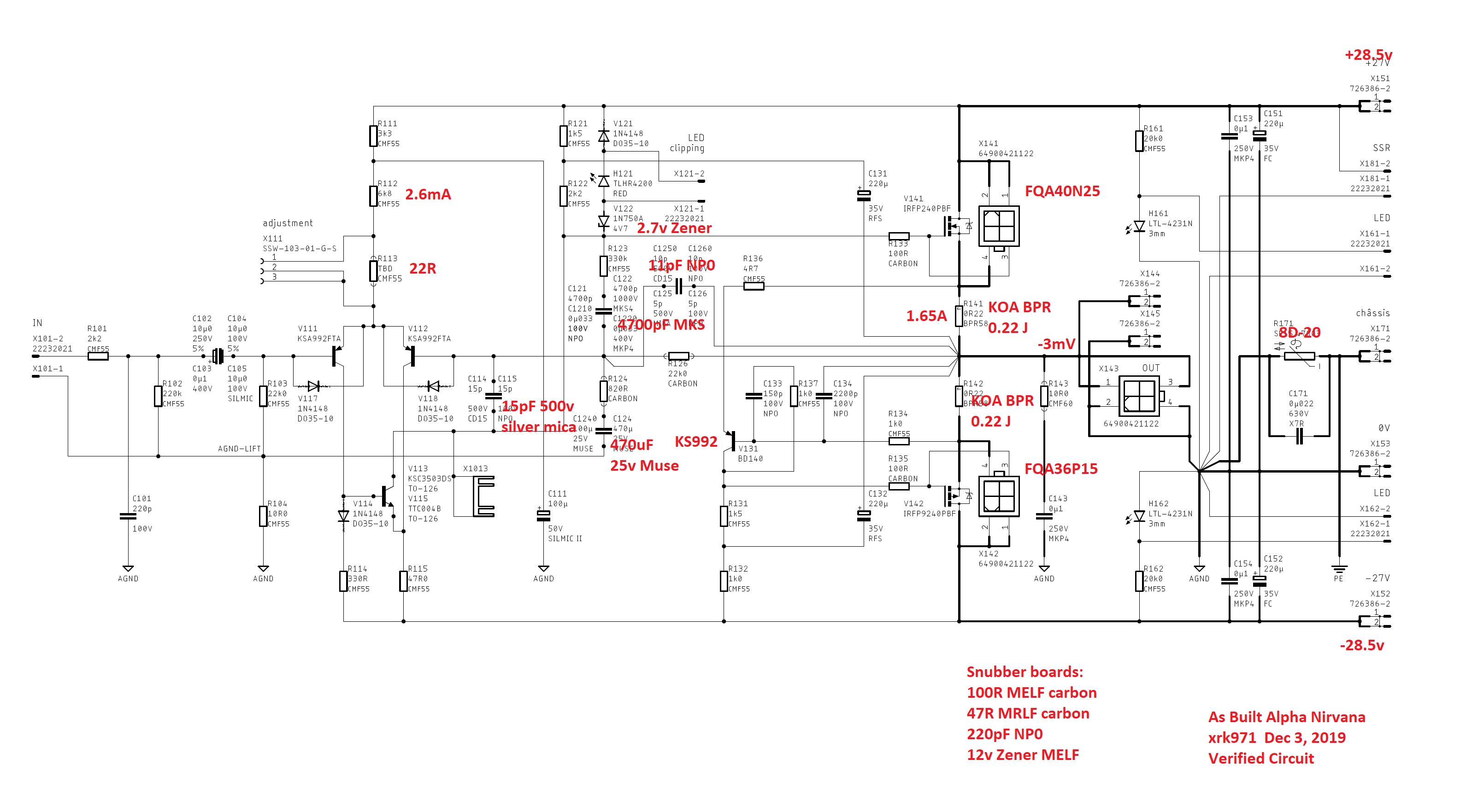
But I wouldn’t worry about using a pot. As Hugh has said, X111 top of the LTP was the wrong place to pot for DC offset. It should have gone on one of the LTP legs (right one) but let’s not worry about it. So just place a 22R resistor in pins 1-2 or 1-3 at X111. It doesn’t matter and let your DC offset lie where it lies. Probably under 20mV from my experience.
If you look at the schematic you will see that pins 2-3 are tied together. So first take your DMM and check continuity to determine which is which. The silkscreen should show pin 1.
But I wouldn’t worry about using a pot. As Hugh has said, X111 top of the LTP was the wrong place to pot for DC offset. It should have gone on one of the LTP legs (right one) but let’s not worry about it. So just place a 22R resistor in pins 1-2 or 1-3 at X111. It doesn’t matter and let your DC offset lie where it lies. Probably under 20mV from my experience.
Good construction of power supply, Andyr ! Compact, making good use of space.
I follow the thread carefully.....
Cheers
I follow the thread carefully.....
Cheers

Hi Andy,
With this setup, how will the hot air escape the chassis and cool air enter the fan intake?
With this setup, how will the hot air escape the chassis and cool air enter the fan intake?
Hi Andy,
If you look at the schematic you will see that pins 2-3 are tied together. So first take your DMM and check continuity to determine which is which. The silkscreen should show pin 1.
Thanks X - I missed seeing that in the schematic. 😱
But I wouldn’t worry about using a pot. As Hugh has said, X111 top of the LTP was the wrong place to pot for DC offset. It should have gone on one of the LTP legs (right one)
Mmmm, yes, that makes sense even to me (with my limited understanding of electronic circuits! 🙂 )
So just place a 22R resistor in pins 1-2 or 1-3 at X111. It doesn’t matter and let your DC offset lie where it lies. Probably under 20mV from my experience.
I have no doubt, X, it would be acceptably low with a 22R res if I was building an 8R AN ... with +/-27v DC rails.
But I am building a 4R AN - which has +/-20v rails; bcoz of this, Hugh has made R112 5K05 (instead of 6K8). Later enthusiasts who build the 4R version can learn from me - but I want to make sure I get the right res value to use for R113 ... by first using a trim-pot in X111, measuring the offset and then removing the trim-pot.
Andy
Hi Andy,
With this setup, how will the hot air escape the chassis and cool air enter the fan intake?
Yes, the million $ question, V! 😀
The base of the case has 2 rows of slots, as you can see; the top of the case will be the Modushop 'fully vented 3mm aluminium cover'.
I'm hoping this will be sufficient. 🙂
Andy
Hmmm...
I am a bit concerned that will not be sufficient. Even the fans placed so close together is not ideal, they will essentially starve each other trying to pull air in opposite directions.
How about this.....
Rotate the fan CPU cooler assembly 90° so the fan will mount to the baseplate. Cut a square hole in the baseplate large enough for the fan opening to draw fresh cool air in from outside the chassis, blowing up through the CPU cooler and out the lid.
How about this.....
Rotate the fan CPU cooler assembly 90° so the fan will mount to the baseplate. Cut a square hole in the baseplate large enough for the fan opening to draw fresh cool air in from outside the chassis, blowing up through the CPU cooler and out the lid.
You mean like this, V?
One fan only - fixed to the floor ... with a big hole cut in the floor panel, underneath?
Andy
Attachments
Last edited:
The way the CPU cooler works efficiently is if the fan is mounted directly onto the aluminum fins, it will not work nearly as well if there is an air gap between the two.
The attached picture shows how the fan would be mounted to the base plate with the CPU cooler fins directly on top of the fan. The fan is blowing through the cooler bringing fresh air in from under the chassis.
The attached picture shows how the fan would be mounted to the base plate with the CPU cooler fins directly on top of the fan. The fan is blowing through the cooler bringing fresh air in from under the chassis.
Attachments
The way the CPU cooler works efficiently is if the fan is mounted directly onto the aluminum fins, it will not work nearly as well if there is an air gap between the two.
The attached picture shows how the fan would be mounted to the base plate with the CPU cooler fins directly on top of the fan. The fan is blowing through the cooler bringing fresh air in from under the chassis.
Aah OK, V - yes, that would be much better! 🙂
I've just played around with the fans I have ... and the so-far-unmounted CPU coolers.
I can - just! - fit a 25mm deep fan underneath the cooling fins, without the top of the CPU cooler base protruding past the top of the sides of the case. Yay!
All I have to do is get some 6m thick oblong spacers cut - so that they lift the mounting brackets off the floor of my case (the bolts going into the tapped holes in the bottom of each mounting bracket will simply go through these spacers). This saves me a major expense of getting new mounting brackets made up! 🙂
My only problem is ... I need to buy 4x 80mm fans to replace my current 120mm fans! 🙁
Thanks for your suggestion, V. 🙂
Andy
- Home
- Amplifiers
- Solid State
- Alpha Nirvana 39w 8ohm Class A Amp