My mains is 118 to 122VAC but highly non sinusoidal - ugly looking “bread loaf” shape - hence generates lots of harmonics from rectification. With Antek I would always go with the “next one up” as they seem to be consistently over-rated (they sag by 3-5v) under larger Class A loads.
Yup, I just built the J2 and was and was getting a rail of about 21.8V on the 300VA 18v from Antek. I actually ordered the 20V to get a rail of 24.6. I spoke with John and he said this is normal with a large load.
Last edited:
My mains is 118 to 122VAC but highly non sinusoidal - ugly looking “bread loaf” shape.
What could be causing this non-sinusoidal wave, X?
Do you live next door to a workshop using arc welders? 🙂
Do you have a solar inverter?
Andy
Nope, just a residential neighborhood with other houses. Maybe it’s when everyone’s air conditioning is running. That was during the summer. I should scope it now in winter and see if it is still bad.
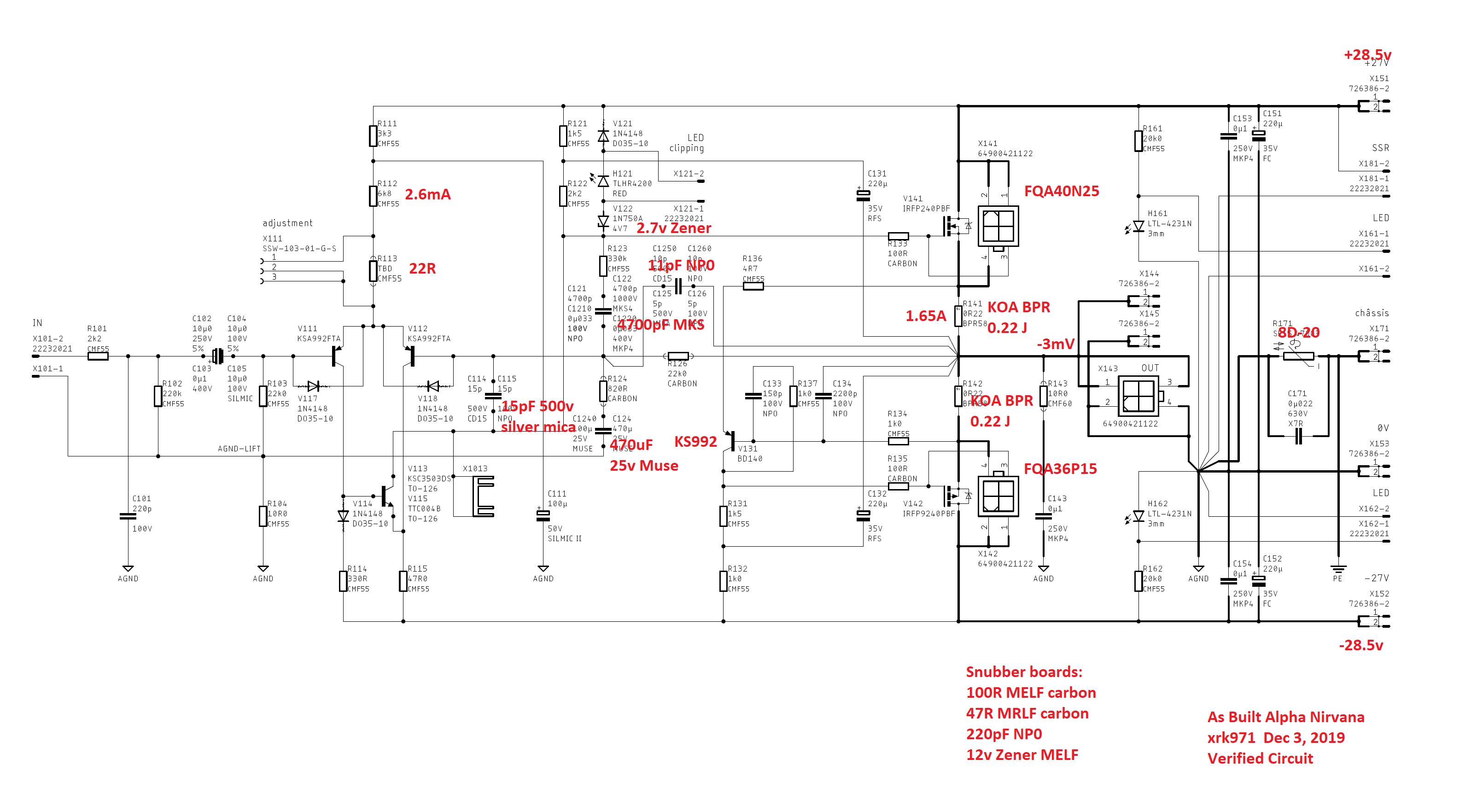
I used a trimpot, 30R was good for 0mV (+/-2mV), the second channel was just about the same at 32R. I would say your ok with anything in that range 22R-32R. If unsure, just install a three socket header in the ADJ location for a trimpot. Get the amp powered up and running and adjust accordingly, pull the pot and measure for a fixed resistor value.
Guys,
I'm just modifying the Mouser shopping cart which X provided in post #1 to be suitable for the 4R build and I have found few anomalies. Can anyone help me with the following:
* 200-SSW10301GS - "Board to Board & Mezzanine connectors"?
What are these for? 🙁
* In the Project list, there is 1x 'GRM3195C2A333JA1D' - an SMD 0.033uF Murata cap.
I can't find this value in the BoM - or in the circuit diagram! 🙁
So where does this fit in?
* Likewise, the next item is 1x WIMA 0.033uF - which I can't find in the BoM or the circuit.
Again, where does this fit in?
Thanks,
Andy
Mezzanine pins X111 - to allow placement of temp resistor for LTP.
0.033uF is C1210 and C1220 optional values
0.033uF is C1210 and C1220 optional values
Guys,
I'm just modifying the Mouser shopping cart which X provided in post #1 to be suitable for the 4R build and I have found few anomalies. Can anyone help me with the following:
* 200-SSW10301GS - "Board to Board & Mezzanine connectors"?
What are these for? 🙁
This three socket connector installs in the ADJ location on the pcb. It allows the temporary attachment of a trimpot like a Bourns 3296 to set offset value.
Guys,
I'm just modifying the Mouser shopping cart which X provided in post #1 to be suitable for the 4R build and I have found few anomalies. Can anyone help me with the following:
* 200-SSW10301GS - "Board to Board & Mezzanine connectors"?
What are these for? 🙁
* In the Project list, there is 1x 'GRM3195C2A333JA1D' - an SMD 0.033uF Murata cap.
I can't find this value in the BoM - or in the circuit diagram! 🙁
So where does this fit in?
* Likewise, the next item is 1x WIMA 0.033uF - which I can't find in the BoM or the circuit.
Again, where does this fit in?
Okay, Andy...
In case you didn't follow X on this one, let me put it in terms I would understand. 🙂
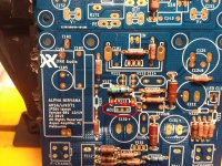
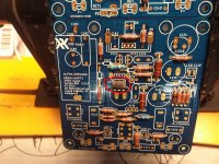
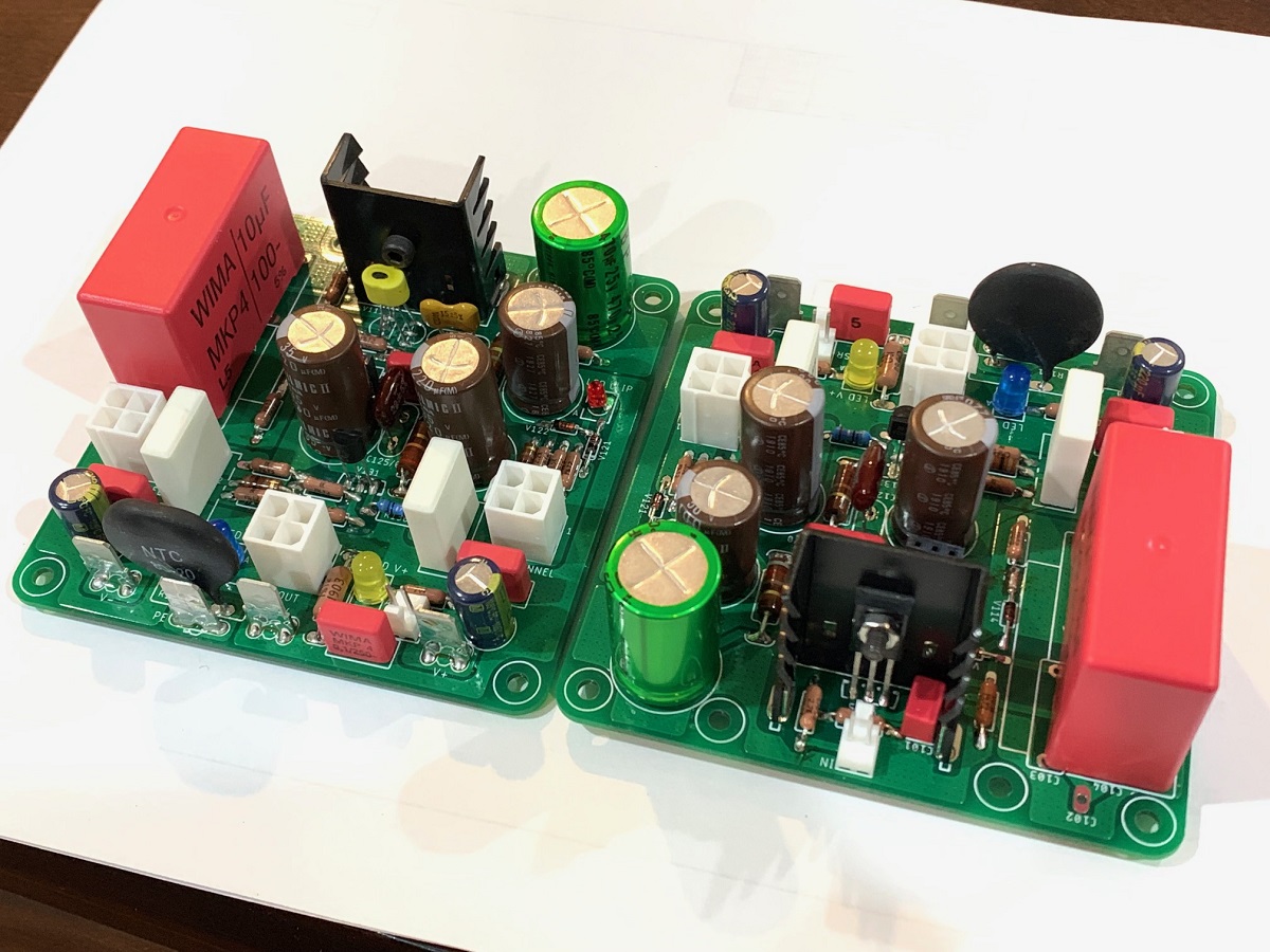
Check out the pics to see what you are seeking. Also, look to the right of the circle and you will see on of the ghost caps you are seeking. The designations for those two caps on the board have a /o after them, so C1210 and C1220 would be C121/O=optional C122/O there is also a C125/O C126/O
Attachments
Last edited:
I could use a little help in the V135-V125 area. It's the same socket. Do we stuff two transistors in there lmao.
THe stuffer reads both in the same place and the board just has V115, but there are two separate parts in the BOM.
I could use some clarity here.
Thanks!
J
THe stuffer reads both in the same place and the board just has V115, but there are two separate parts in the BOM.
I could use some clarity here.
Thanks!
J
I meant to say V113-V115
Also, C122 C122/O We have the option of 4.7uF(MKS) to .033uF(MKP) respectively, that's a pretty big difference, can you explain a little about the effect?
Also, C122 C122/O We have the option of 4.7uF(MKS) to .033uF(MKP) respectively, that's a pretty big difference, can you explain a little about the effect?
Last edited:
I meant to say V113-V115
Also, C122 C122/O We have the option of 4.7uF(MKS) to .033uF(MKP) respectively, that's a pretty big difference, can you explain a little about the effect?
That’s 4700pF or 4.7nF. There were two values of 4.7nF or 0.033uF (33nF). I ended up picking 4.7nF. Seems to work well for me. I can’t remember why there were two values here. It may be because we had a few different LTspice sims that both seemed to work.
Last edited:
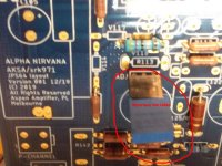
Thanks have a question on orientation of the 511-BD140 V131. THe PCB indicates the back should be facing off the board the wider section is usually the back, but when I looked up the pinout of it, pin 1 looking at the face of the transistor, is on the right side. The stuffer has a dot indicating pin 1 on the right looking from the back of the transistor.
In other words, if I put pin 1 like indicated on the stuffer, the back is facing inward and not outward.
In other words, if I put pin 1 like indicated on the stuffer, the back is facing inward and not outward.
Pin 1 is always the left one when looking at the front face of the transistor. Front face is the face when lettering is present and legible. BD140 should have laser etched letters in front. They are hard to see. Older ones had exposed metal thermal pad on back. Newer ones are all black epoxy. Install with back (wider side) to match the silkscreen and you are fine. If in doubt, use a transistor tester to see which pin is which. Then follow traces on V131 to match and cross reference with schematic. Do a little detective work when in doubt. In the end, the traces and the schematic are the truth. Occasionally, a board will have typo on silkscreen. And as a builder of a never run before amp you have to do this sort of detective work all the time. For Alpha Nirvana, it’s been double tested by Vunce and myself so you are assured that it will work.
I have used both KSA992 and BD140 here. They both work well and happen to have the same ECB pinout. If you look at my photo, you can see a KSA992 installed there. The KSA992 has the rounded part for the back.
I have used both KSA992 and BD140 here. They both work well and happen to have the same ECB pinout. If you look at my photo, you can see a KSA992 installed there. The KSA992 has the rounded part for the back.
Last edited:
@X well, here's my confusion, this looks like the front and pin 1 in on the right. I must have an older one too as the back is metal. That's also why I assumed I was looking at the face as there was no metal.
https://www.mouser.com/datasheet/2/389/bd135-954513.pdf
https://www.mouser.com/datasheet/2/389/bd135-954513.pdf
Last edited:
- Home
- Amplifiers
- Solid State
- Alpha Nirvana 39w 8ohm Class A Amp