Andy,
If you dimension the amp for 4R but run it from 25V rails you could use the same trafo but adjust the voltage drop across the SLB to amend the voltage. The SLB would drop a bit more watts, but if the amp was well cooled the higher rails would be OK and it could give you more than 60W into 4R.
X's idea is a very good one, and JPS's layout makes this all quite easy.
Hugh
I suspect that my trafo under 1.65A load is 28.5v will sag to 25v under 3A. The heat load on the SLB will double of course. Additional Noctua 120mm fan per heatsink should take care of the extra heat. 60w into 4ohms is quite a punch.
If you save the spreadsheet as a zip file, you could post here for everyone.
OK, have done this, X. 🙂
Perhaps you can confirm you read the attached OK?
Andy
Attachments
Hi Andy,
I can read the XLS files - thank you!
Excellent! So I followed the destructions correctly. 😀
Andy
AN BOM's.
Andy, both BOM versions you have put together should help every member who is planning on building this excellent amp design.
Thanks again for your work on that, it must have taken hours researching and typing all the info into your Excel sheets.
Andy, both BOM versions you have put together should help every member who is planning on building this excellent amp design.
Thanks again for your work on that, it must have taken hours researching and typing all the info into your Excel sheets.
I linked AndyR's BOMs to the first post of this thread and also first post of the GB thread for easy access by future builders.
Thank you, AndyR.
Thank you, AndyR.
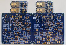
PCB layout
Hi X,
Thank you for your great contribution to the community 🙂
Do we have a tested PCB layout for the diy use.
I would like to make this amp using handmade pcb.
Regards you
Sha
Hi X,
Thank you for your great contribution to the community 🙂
Do we have a tested PCB layout for the diy use.
I would like to make this amp using handmade pcb.
Regards you
Sha
Hi X,
Thank you for your great contribution to the community 🙂
Do we have a tested PCB layout for the diy use.
I would like to make this amp using handmade pcb.
Regards you
Sha
Curiouser and curiouser, Sha! 😀
We have tested PCBs for DIY use! Why on earth would you want to make up your own PCB?
Andy
Not everyone can afford the ~$133AUD (~$93usd) for just the boards alone.
And I know some people do prefer to etch their own boards to get the full DIY experience!

And I know some people do prefer to etch their own boards to get the full DIY experience!
Attachments

Last edited:
Not everyone can afford the $133AUD (~$93usd) for just the boards alone.
True - but this is not a cheap amp to build ... with its cooling requirements.
And I know some people do prefer to etch their own boards to get the full DIY experience!
If you want "the full DIY experience ", I suggest you use 3mm teflon sheet to hold the components in place ... and use ptp wiring underneath the teflon board. 😀 (No PCB required!)
Andy
And I know some people do prefer to etch their own boards to get the full DIY experience!
When speaking of full DIY experience, some people do prefer to draw their own pcbs before etching them.
Why on earth would you like to make your own amp?Why on earth would you want to make up your own PCB?
Do we have a tested PCB layout for the diy use.
I would like to make this amp using handmade pcb.
We do indeed have a tested PCB layout:
This is a public and open DIY project. You are free to make your own layout and PCB or do it point to point on perforated veroboard. Note that these are two-sides layouts - not easy to home etch.
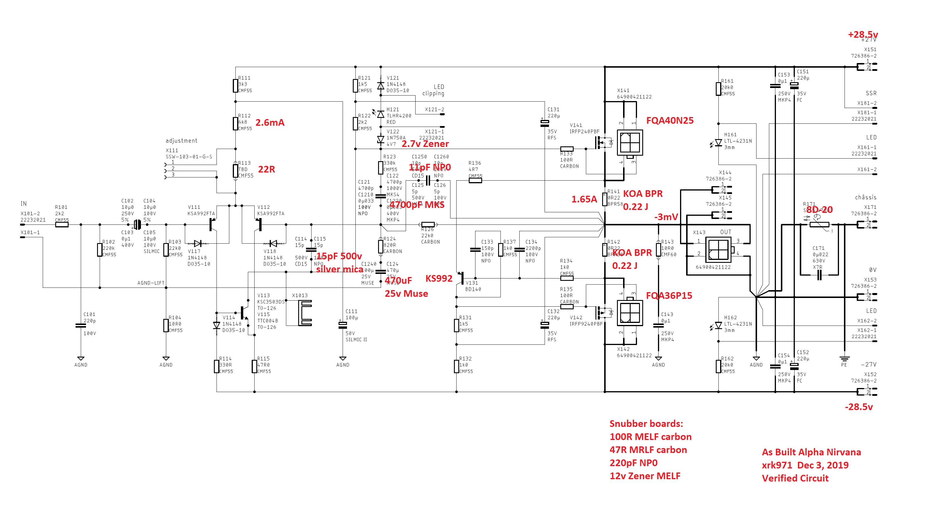
I think it was mentioned as a response to an earlier question. It is set by R103, so about 22k.
Hi X,
If I want to run the amplifier at a lower power, say 15W class A, what changes should be made in the circuit? Will a 150VA tranny do in that case?
If I want to run the amplifier at a lower power, say 15W class A, what changes should be made in the circuit? Will a 150VA tranny do in that case?
If you only need 15w I would go for the Alpha 20 and drop voltage to +/-18v or so. For Alpha Nirvana to run there we would need to recalculate the resistor set points to make sure there is 2.6mA bias current through LTP. You would need +/-17v rails and maybe 1.2A bias current. That’s 20w per MOSFET of 40w total. Much less cooling requirement. That’s 80VA for both channels and multiply x 3 to size minimum trafo. So 250VA trafo is about right. If you use SLB there is 3v drop plus 3v sag. So 17v + 6v is 23v. Divide by 1.4 is 16.4v ac trafo.
Hi X,
If I want to run the amplifier at a lower power, say 15W class A, what changes should be made in the circuit? Will a 150VA tranny do in that case?
Sanjeev,
This thread is about the 39w-into-8ohms Alpha Nirvana - having +/-27v DC rails.
As X said, setting it up as a lower-power (lower DC rails) version requires a number of resistor value changes. Hugh has already done this - the AN 4R version is referenced within the thread. IOW, whilst noone has built it yet, the different resistor values are known (and the DC rails are +/-20v).
I would suggest this is the one you should build, if you are looking for a lower-power version. 🙂 I am going to build 2 (stereo amps) of the 4R version - as 2 of the drivers in my 3-way active system that I wish to power with them are 3.2 & 2 ohms, respectively.
Andy
- Home
- Amplifiers
- Solid State
- Alpha Nirvana 39w 8ohm Class A Amp