I think the FQA’s are rated for 280w and cost maybe $1 more than the IRFP’s but can be safely run at 45w dissipation. Whereas the latter are rated 150w and more like 30w if you want long life. If you have some IRFPs and want to get started, by all means use them until you get the bigger ones. Changing MOSFETs is certainly easy with this amp.
@garys, yes that socket is to test various values of resistors. You may have some differences in your setup that may require a different value than 22R to achieve 0mV dc offset. I am at -3mV and -5mV. I think Vunce actually hit 0mV. He used a different resistor I think.
@garys, yes that socket is to test various values of resistors. You may have some differences in your setup that may require a different value than 22R to achieve 0mV dc offset. I am at -3mV and -5mV. I think Vunce actually hit 0mV. He used a different resistor I think.
Thanks X for the reply.
Hi Vunce,
Did you use a different value for R113 (22 ohm) to get 0mV DC offset?
Hi Vunce,
Did you use a different value for R113 (22 ohm) to get 0mV DC offset?
BOM power MOSFET listing
Thanks for the clarification, X, that the FQA MOSFETs are the “official parts” for the AN. Perhaps the “official BOM” should reflect that to avoid future confusion.
Thanks for the clarification, X, that the FQA MOSFETs are the “official parts” for the AN. Perhaps the “official BOM” should reflect that to avoid future confusion.
Last edited:
@garys, yes that socket is to test various values of resistors. You may have some differences in your setup that may require a different value than 22R to achieve 0mV dc offset. I am at -3mV and -5mV. I think Vunce actually hit 0mV. He used a different resistor I think.
Would it be possible to have a small value pot in that parallel position so you could just 'dial in' the offset?
Yes, it can be done - a pot in the stage current path to the LTP - but 3mV is bagatelle and I have found that up to 50mV has no influence on sound or durability of the drivers.
You can do it of course, it's entirely up to you. But there is provision for a fixed resistor which is always more reliable than a pot. Over time, and with dust, they can actually go open circuit.
Hugh
You can do it of course, it's entirely up to you. But there is provision for a fixed resistor which is always more reliable than a pot. Over time, and with dust, they can actually go open circuit.
Hugh
Would it be possible to have a small value pot in that parallel position so you could just 'dial in' the offset?
Exactly avtech!
I installed a 500R Bourns 3296 pot there, my values turned out to be 30R and 20R. One channel is bang on 0mV, the other is a minuscule 2mV.
Like Hugh said, replace the pot with a fixed resistor once your dialed in.
Last edited:
Hi xrk971.
Can you please confirm that your AN 8R PCBs are set up for the (slightly modified) circuit schematic which Hugh posted in post #88, on Nov 3rd.
Thanks,
Andy
Can you please confirm that your AN 8R PCBs are set up for the (slightly modified) circuit schematic which Hugh posted in post #88, on Nov 3rd.
Thanks,
Andy
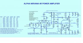
Here is post 88 schematic:
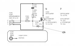
I don’t believe that is the final schematic that Hugh produced. As that one has a 47R between the emitter of Q4 and source of N channel MOSFET. Here is production board schematic:
https://www.diyaudio.com/forums/att...-class-amplifier-gb-alpha-nirvana_sch_001-pdf
The production schematic is this with my “as-built” notes:
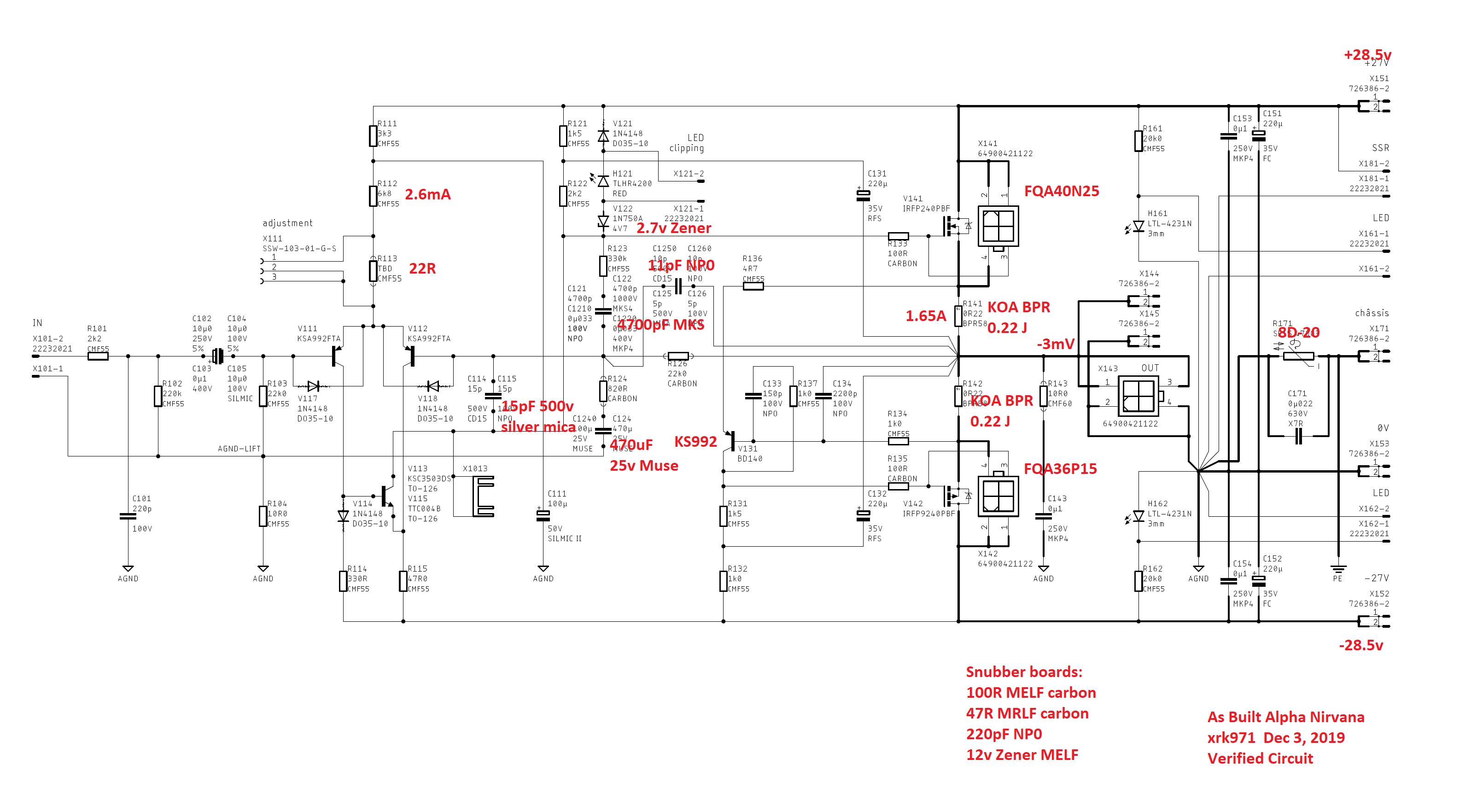
I think some of the final changes were only captured via email exchanges between myself Hugh, and JPS64. But you will find that the production schematic and PCB has everything g that the post 88 schematic has and more. So you could jumper something if you wanted to.
Note that C125 was eventually 10pF silver mica. V131 works as KSA992 or BD140
Ingested both and I currently have it with BD140 (same pin out).
I don’t believe that is the final schematic that Hugh produced. As that one has a 47R between the emitter of Q4 and source of N channel MOSFET. Here is production board schematic:
https://www.diyaudio.com/forums/att...-class-amplifier-gb-alpha-nirvana_sch_001-pdf
The production schematic is this with my “as-built” notes:
I think some of the final changes were only captured via email exchanges between myself Hugh, and JPS64. But you will find that the production schematic and PCB has everything g that the post 88 schematic has and more. So you could jumper something if you wanted to.
Note that C125 was eventually 10pF silver mica. V131 works as KSA992 or BD140
Ingested both and I currently have it with BD140 (same pin out).
Last edited:
Thanks, X.
I have searched through the thread but cannot find any later version of Hugh's schematic (than the one in post #88).
Yes, of course you/JPS64 have turned this into a different schematic (which uses different component numbers) - which matches the PCBs you produced.
Anyway, I updated the 8R BoM with your 'As Built' notations in red.
NB: Except for R171, which I have left as the SL15_47003 specified in the BoM (as per your email instruction).
Hopefully, this is useful to some people. 🙂
My next task (after I get a question answered by Hugh) is to produce a 4R BoM.
Regards,
Andy
PS: I'm happy to send the Excel s/sheet to anyone who wants it. An Excel file is not an accepted format on the Forum - hence, I saved it as a PDF - so I will have to email it to you.
Attachments
Last edited:
There is another thing I cannot reconcile between the 'As Built' schematic and Hugh's (blue) 8R cct diagram:
* Hugh's 8R cct diagram has C10 & R13 connecting the +ve DC rail to the Gate of M1.
Likewise, C12 & R22 connect the -ve DC rail with the Gate of M2.
These are not shown on the 'As Built' schematic - so, presumably they don't appear on the PCBs? 😕
Andy
* Hugh's 8R cct diagram has C10 & R13 connecting the +ve DC rail to the Gate of M1.
Likewise, C12 & R22 connect the -ve DC rail with the Gate of M2.
These are not shown on the 'As Built' schematic - so, presumably they don't appear on the PCBs? 😕
Andy
C10, R13, C12, and R22 are on the snubber boards.
Aah, thank you, tikiroo!
Andy
Last edited:
C10, R13, C12, and R22 are on the snubber boards.
BTW, tikiroo, Hugh's 4R cct diagram has:
* Z2 connecting the Gate to the Source of M1 (V141 in the 'As Built' schematic), and
* Z3 connecting the Gate to the Source of M2 (V142 in the 'As Built' schematic).
Will these Zener diodes be able to be soldered in place on the Snubber boards? (They're not present on Hugh's 8R cct diagram - so I presume the Snubber boards don't allow for them!)
Andy
Attachments
The Zeners are also on the snubber boards. My notes at the bottom of the as built diagram indicate this.
You can see them here under the legs:
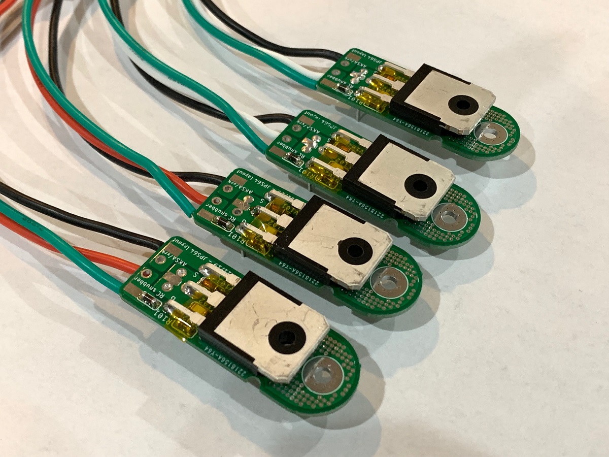
You can see them here under the legs:
Hi Andy,
You mean Hugh's 4ohm version of the Alpha Nirvana can be built using the PCB designed for the 8ohm version? Yes.
You mean Hugh's 4ohm version of the Alpha Nirvana can be built using the PCB designed for the 8ohm version? Yes.
Hi Andy,
You mean Hugh's 4ohm version of the Alpha Nirvana can be built using the PCB designed for the 8ohm version? Yes.
Exactly, x! 🙂
So my task today is to create the 4R BoM from the 8R BoM. As there is no '4R As Built' schematic, this means I have to add a column which has Hugh's components names ... and match these names against the component names used in the BoM & the 'As Built' schematic.
Andy
- Home
- Amplifiers
- Solid State
- Alpha Nirvana 39w 8ohm Class A Amp