The PE ground connections are there for safety in case of a catastrophic short in the transformer and shunts the short to ground to prevent fire/electrocution. The PE grounds also reduce RF/EMI noise.
Sorry, X - just 1 more Qu re. these 'PE ground' wires.
Given the SLBs have these wires - surely they will do the work of shunting any (traffo) short to ground, to prevent fire/electrocution?
So why are wires also needed on the AN boards?
I can understand they were included on the AN boards to allow for amp builders who didn't use SLBs - but when you do use SLBs ...?
Andy
Because the amp boards are connected to the PSU (so could potentially be energized) and also benefit from a ground connection to reduce noise pickup. The NTC and 22nF cap act as a ground loop breaker to reduce hum from gorund loops.
Because the amp boards are connected to the PSU (so could potentially be energized) and also benefit from a ground connection to reduce noise pickup. The NTC and 22nF cap act as a ground loop breaker to reduce hum from gorund loops.
Aah, OK - thanks, X.
So:
1. they do perform a useful function on the AN boards.
2. which means I need to get a deeper case, so I can mount the AN boards on the bottom panel, at the back (rather than on the back panel).
Andy
What size case do you have now?
I have tentative plans for a single-chassis dual-mono AN in a 4U 400mm HiFi2000 chassis from the DIYA store, and don't really have the space for a 4U 500mm.
I have tentative plans for a single-chassis dual-mono AN in a 4U 400mm HiFi2000 chassis from the DIYA store, and don't really have the space for a 4U 500mm.
What size case do you have now?
I have tentative plans for a single-chassis dual-mono AN in a 4U 400mm HiFi2000 chassis from the DIYA store, and don't really have the space for a 4U 500mm.
I'm currently using a 350mm deep, 3U Slimline chassis, pf. 🙂
Andy
I have tentative plans for a single-chassis dual-mono AN in a 4U 400mm HiFi2000 chassis from the DIYA store
I'm using the same chassis 4U-400 with the 10mm front panel,
my amp is biased at 1.9A, that is about 90-100W heat/channel.
The heatsinks are 20-21°C above room temperature.
Two tips to make it better at heat transfer:
- use Ceramic or Alumina Al2O3 pads
- include the front panel as heatsink, this way I've installed my mosfets 1-2cm closer to the front, instead of the middle of the heatsink
danny, are you saying you actually mounted some of the active devices to the front panel?
Or you just mentally count on it as being part of the heat dissipating metal (which I guess it technically always is)
Do you put thermal compound in the joint between the front panel and the main heatsinks on the sides?
Or you just mentally count on it as being part of the heat dissipating metal (which I guess it technically always is)
Do you put thermal compound in the joint between the front panel and the main heatsinks on the sides?
It's your third option:
I've put thermally conductive paste between the two heatsinks (each side has two heatsinks) and also the frontpanel.
So the frontpanel and the four heatsinks become one radiator.
I've put thermally conductive paste between the two heatsinks (each side has two heatsinks) and also the frontpanel.
So the frontpanel and the four heatsinks become one radiator.
Well, I am very happy to be able to report that - after a marathon effort lasting more than 12 months - I am finally listening to 2x AN 4Rs driving the mids & ribbons of my 3-way active Maggies. YAY! 🙂
Which I think are the first AN 4R amps to be created? 🙂
OK - what was the major cause of the troubles I had (then I'll get onto a couple of additional issues)?
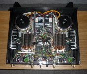
Quite simple - the layout I had chosen! 😱 I had bought 300VA power toroids which were a bit over 120mm in diameter - so they couldn't be mounted vertically. But in mounting them horizontally, the only way I could fit everything into the 350mm deep SlimLine chassis (HiFi2000) was to mount the AN PCBs vertically, on the back panel.
See 1st attached pic.
And the result was:
* when the back panel was open - ie. laying backwards - I got a sine wave out from the spkr terminals when I fed one in from a sig-gen.
* but when the back panel was closed, I got a square wave - which caused my ribbon to blow, last year.
This took quite a while to diagnose ... because of a couple of other issues associated with building a 4R AN.
When it finally became clear that closing the back panel with the AN boards mounted on them resulted in a whole lot of wires being compressed into the space between the AN boards and the bracket on which the CPU coolers (holding the Snubber boards) - which caused the square wave problem - I realised I had to re-organise the layout in the SlimLine cases.
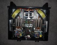
Which led to layout #2 - see 2nd attached pic.
Here, I mounted the power toroids vertically at the front of the case (on some 'L' brackets) and had 2 rectangular slots cut into the bottom panel of each case ... to allow the toroids to sink through the bottom panel - leaving a few mm gap between the top edge of each toroid and the case's top panel.
This enabled me to move the CPU coolers forwards ... leaving space for the AN boards to be mounted horizontally on the bottom panel, at the back of the case.
This allowed the back panel to be bolted closed ... with no issues! 🙂
But in going thru this saga, I had to retrofit a couple of components changes to both SLB boards and AN boards, for the 4R build:
1. the compensation cap (C4 in the 4R schematic) had to be increased from 15pF to 22pF, to stop oscillation.
2. because - at least in the higher current environment associated with a 4R build - the cfp arrangement in the SLB can be unstable, Hugh recommended I install a 1nF silver mica cap between pins 1 & 2 of Q10 & Q12.
These retrofits led to another - quite surprising - problem! 🙁
Once again, the damn Molex connectors were the cause (Jeez, I hate them! 😡 )
On one channel of one amp, when testing (after having done the retrofits), I was getting only 7v out - when all the other channels were delivering 8v from the same sig-gen volume.
With some help from Hugh over a couple of weeks, I was able to determine that this was due to faulty Molex connections (which seemed bizarre to me because I thought - if one mosfet is not connected properly ... how do I get any signal out??). But it seems you can when feeding a signal from a sig-gen in and just measuring the output from the spkr terminals with a CRO! (This would not be the case with a spkr actually connected.)
Anyway, issues are finally resolved - and they sound wonderful! 🙂
Andy
Which I think are the first AN 4R amps to be created? 🙂
OK - what was the major cause of the troubles I had (then I'll get onto a couple of additional issues)?
Quite simple - the layout I had chosen! 😱 I had bought 300VA power toroids which were a bit over 120mm in diameter - so they couldn't be mounted vertically. But in mounting them horizontally, the only way I could fit everything into the 350mm deep SlimLine chassis (HiFi2000) was to mount the AN PCBs vertically, on the back panel.
See 1st attached pic.
And the result was:
* when the back panel was open - ie. laying backwards - I got a sine wave out from the spkr terminals when I fed one in from a sig-gen.
* but when the back panel was closed, I got a square wave - which caused my ribbon to blow, last year.
This took quite a while to diagnose ... because of a couple of other issues associated with building a 4R AN.
When it finally became clear that closing the back panel with the AN boards mounted on them resulted in a whole lot of wires being compressed into the space between the AN boards and the bracket on which the CPU coolers (holding the Snubber boards) - which caused the square wave problem - I realised I had to re-organise the layout in the SlimLine cases.
Which led to layout #2 - see 2nd attached pic.
Here, I mounted the power toroids vertically at the front of the case (on some 'L' brackets) and had 2 rectangular slots cut into the bottom panel of each case ... to allow the toroids to sink through the bottom panel - leaving a few mm gap between the top edge of each toroid and the case's top panel.
This enabled me to move the CPU coolers forwards ... leaving space for the AN boards to be mounted horizontally on the bottom panel, at the back of the case.
This allowed the back panel to be bolted closed ... with no issues! 🙂
But in going thru this saga, I had to retrofit a couple of components changes to both SLB boards and AN boards, for the 4R build:
1. the compensation cap (C4 in the 4R schematic) had to be increased from 15pF to 22pF, to stop oscillation.
2. because - at least in the higher current environment associated with a 4R build - the cfp arrangement in the SLB can be unstable, Hugh recommended I install a 1nF silver mica cap between pins 1 & 2 of Q10 & Q12.
These retrofits led to another - quite surprising - problem! 🙁
Once again, the damn Molex connectors were the cause (Jeez, I hate them! 😡 )
On one channel of one amp, when testing (after having done the retrofits), I was getting only 7v out - when all the other channels were delivering 8v from the same sig-gen volume.
With some help from Hugh over a couple of weeks, I was able to determine that this was due to faulty Molex connections (which seemed bizarre to me because I thought - if one mosfet is not connected properly ... how do I get any signal out??). But it seems you can when feeding a signal from a sig-gen in and just measuring the output from the spkr terminals with a CRO! (This would not be the case with a spkr actually connected.)
Anyway, issues are finally resolved - and they sound wonderful! 🙂
Andy
Attachments
Last edited:
Andy,
Congrats.
I guess it goes to show you that there are certain trials and tribulations one has to go through when stuffing a Class A design into a smaller chassis. I don’t have the courage nor patience I think since I am from the classical amp building side of things where we use big heatsinks and don’t use long wirings for MOSFETS, specifically the SLB’s and AN boards in this case (due to ‘potential’ oscillation issues). That being said, the zeal of conquering that which may seem insurmountable is something I admire! And looking at your pictures I learned a few things!
Congratulations and let us know what it sounds like versus other designs you have built!
Best,
Anand.
Hi Andy, great looking amp you've built. I've got a couple of quick questions, if you don't mind. I'm looking to build the 4R version of the amp, did you use the same transformer secondary voltage as the 8R version, and are they PC CPU coolers that have used?
Congratulations Andy! Glad you got it all sorted out. I suppose you skipped the SSR DC protection circuits this time?
Sorry you had such a hard time with the Molex connectors. I can assure you that when properly crimped and installed with the correct female crimp sockets into the appropriate shell housings, they are super reliable and used as an industry standard for PC, automotive, appliance and industrial power and signal connectors.
How do you like the sound?
Cheers,
X
Anyway, issues are finally resolved - and they sound wonderful! 🙂
Andy
Great news Andy! It's been a while, but now you can enjoy the fruits of your labor.
ENJOY

Andy,
Congrats.
I guess it goes to show you that there are certain trials and tribulations one has to go through when stuffing a Class A design into a smaller chassis. I don’t have the courage nor patience I think since I am from the classical amp building side of things where we use big heatsinks and don’t use long wirings for MOSFETS, specifically the SLBs and AN boards in this case (due to ‘potential’ oscillation issues). That being said, the zeal of conquering that which may seem insurmountable is something I admire! And looking at your pictures I learned a few things!
Congratulations and let us know what it sounds like versus other designs you have built!
Best,
Anand.
Thank you, Anand.
Yes, I could've used a 4U - or even 5U case - but I liked the concept of active cooling and preferred to have a 3U chassis, if I could get it.
In terms of "long wiring" to remote SLB transistors / AN mosfets, I like the concept of off-board devices. 🙂 The wires from my snubber boards to each AN board are only 4" long, max - but, yes, those to the SLB transistors are longer ... perhaps 10".
How does it sound - in comparison to previous Hugh Dean designs that I have built? I have to wait a bit before replying in full. My listen yesterday was to music supplied by a DAB+ tuner - not vinyl, my primary listening medium. This was purely to prove to myself that they were a. working and b. stable into 3 ohm drivers (as the previous time I had connected one of the amps up to one of my Maggies - I blew a ribbon! 😡 ).
Before I can say how good they are, I need to run some REW measurements to ensure that the mids & ribbons are at the same level as my previous NAKSA amps ... as the gains in the two amps are slightly different.
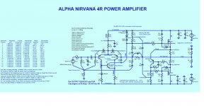
Andy, which exactly schematic have you built? From which post?
Hi Minek - see attached. (Sorry, I don't know which post referred to it.)
If you are going to build the 4R version, you need to refer to my spreadsheet which gives the relationship between the component nos which Hugh Dean used in his 4R schematic and the 8R schematic that is the basis for the AN PCB.
I believe X has listed this on the 1st post in this thread.
Hi Andy, great looking amp you've built. I've got a couple of quick questions, if you don't mind. I'm looking to build the 4R version of the amp, did you use the same transformer secondary voltage as the 8R version, and are they PC CPU coolers that have been used?
Thank you, jaq. 🙂
No, you want the DC rails coming out of the SLBs to be 20-21v (not the 27v in the 8R version). Hence you need 18v secondaries on the power traffos.
And with the current draw on the AN 4R cct, you need one SLB (and, I would suggest, 1 traffo) per AN board.
Yes, they are Dell CPU coolers (model FD841 version 1.0) bought from ServerWorlds, in MN. Vunce put me onto them. 🙂
Andy,
Glad to know you got things sorted out.
Enjoy!
Thank you, zman. 🙂
Congratulations Andy! Glad you got it all sorted out. I suppose you skipped the SSR DC protection circuits this time?
Yes, I decided to leave them out of the re-arranged layout.
Which means I have 4x Gen 1 SSRs for sale, cheap - if anyone wants them. 🙂
Sorry you had such a hard time with the Molex connectors. I can assure you that when properly crimped and installed with the correct female crimp sockets into the appropriate shell housings, they are super reliable and used as an industry standard for PC, automotive, appliance and industrial power and signal connectors.
Well, I had a number of problems with the connectors used for Q10 & Q12 on the SLB boards and those used for the mosfets on the AN boards - despite using the correct crimp connects for the housings. And using one of the crimp tools you specified in one of your posts.
And re. automotive use - Molex are made & marketed in the USofA and are inexpensive. However, my understanding is that European car makers use EURO automobile connectors in their computers and ECUs. These are far more reliable ... though more expensive.
How do you like the sound?
Cheers,
X
As I said above, I'm not quite at the stage of critical listening. 🙂
Great news Andy! It's been a while, but now you can enjoy the fruits of your labor.
ENJOY
Thank you, V! 🙂 Yes, I am looking forward to some great listening.
Regards,
Andy
Attachments
Last edited:
Nice job Andy, I have been reading your trials since you started the project. I was thinking of a pair for 4R if you remember back that far. lol I said I was going to let you figure it all out before/if I build them.
Glad you won!
J
Glad you won!
J
- Home
- Amplifiers
- Solid State
- Alpha Nirvana 39w 8ohm Class A Amp