Yes that is definitely a work of art Minek123 - congratulations on a job well done. You will be happy if it sounds as good as it looks.
Thanks guys.Yes that is definitely a work of art Minek123 - congratulations on a job well done. You will be happy if it sounds as good as it looks.
It does sound great.
And overall it's very simple, and cheap to build.
Best bang for the buck, as long as I avoid audiophile class
input capacitors size of baby's leg, and made for Soviet military in the 60s... 🙂
Well, I've just done some measurements, using:
* my 6.2 ohm dummy load
* a CRO, and
* a sig-gen - set to 1kHz.
First of all: gain, I measure to be x26.4 (140mV ptp in and 3700mV ptp out). Does this match what other people have measured?
Secondly - yes, the red LEDs do come on ... at 2v less than when the output waveform starts to clip! Yay (I didn't blow them)! 🙂
The red LEDs came on when the output ptp voltage was 38v; the output waveform on the CRO showed the top part of the sine wave starting to flatten at 40v ptp.
This is with 44v across the DC rails on the AN boards.
Thirdly - perhaps someone can tell me if my maths is correct ... or not. 🙂
V = I*R tells us that 40v across a 6.2 ohm load means a current of 6.45a - right?
But watts = I^2 * R tells us the power going through that 6.2 ohm load ... is 258w! That seems outrageously high? 😕
Andy
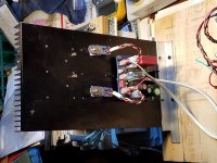
Here are the final photos.
AN is on top of small Alu box without VU meters - that's AN's
PSU.
Below it's my other two PSUs, that are used for all other amps -
the one with lights on is handling output (speaker protection and VUs) for AN.
It's not really needed - I could plug speakers directly to AN, but I want to use
protection...
New, 4-pins Noctua fans are actually controlled by the temperature sensor (it turned out
that previous 3-pin fans were not!), and they are running slightly faster than old ones.
As a result, FET's temperature of in low 60s, and they are also dead quiet.
These VU meters are from burned out Technics chip amp and from dead Akai tape player..
Beaudifull! A work of art. 🙂
Andy
V = I*R tells us that 40v across a 6.2 ohm load means a current of 6.45a - right?
But watts = I^2 * R tells us the power going through that 6.2 ohm load ... is 258w! That seems outrageously high? 😕
Andy
V = I*R and P = I^2 * R works for DC current.
For AC current (sinus) we can calculate power like this:
Vpp=40V
Vrms = (Vpp/2) * 0.707 = 14V
P = (Vrms)^2 / R
So in your case:
P = 14^2/6.2 = 196/6.2 = 31W
See AC power - Wikipedia
Very good explanation of audio power from Andrew T.:
Measuring output power - diyAudio
Last edited:
V = I*R and P = I^2 * R works for DC current.
For AC current (sinus) we can calculate power like this:
Vpp=40V
Vrms = (Vpp/2) * 0.707 = 14V
P = (Vrms)^2 / R
So in your case:
P = 14^2/6.2 = 196/6.2 = 31W
Aaah, thank you, minek. 🙂 31w to clipping makes much more sense!
And thanks for the links.
Andy
After my (limited! 🙁 ) listening, I decided to do some measurements of my AN 4R with CRO, sig-gen and dummy load … which I found very interesting! 🙂
Both channels clip at the same level. But, interestingly enough, it’s not the top half of the 1kHz sine wave that clips in each load scenario! As the load resistance goes down ... the clipping changes from voltage clipping (which is clipping on the top half of the signal sine wave) to current clipping (clipping on the bottom half of the sine wave).
And the red clip LED only signals when voltage clipping is about to happen.
The below results are with just under 22v +/- DC rails:
6.2 ohm load:
Sine wave clips at 40v pp (top peak!)
Red LED goes on at 38v pp ... so it indicates that clipping is about to happen! 🙂
Power is 31w, at clipping
Current is 3.22a
3.7 ohm load:
Sine wave clips at 37.5v pp (bottom peak!)
Red LED goes on at 36v pp ... so it indicates that clipping is about to happen!
Power is 47w, at clipping
Current is 5.06a
3.1 ohm load:
Sine wave clips at 36v pp (bottom peak)
Red LED goes on at 36v pp ... so there is no warning!
Power is 52w, at clipping
Current is 5.8a
2.5 ohm load:
Sine wave clips at 29v pp (bottom peak)
Red LED goes on after clipping starts - so no warning!
Power is 42w, at clipping
Current is 5.8a
2.1 ohm load:
Sine wave clips at 24v pp (bottom peak)
Red LED goes on after clipping starts - so no warning!
Power is 34w, at clipping
Current is 5.7a
Andy
Last edited:
Andy,
As your version was designed for 4R with dips to 3R, your figures with 2.1R at 34W are very good. Thank you for showing these figures to the members here; it is impressive for a Class A amplifier into a very stiff 2.1R load.
Negative current clip appears quicker than positive clip because positive waveform is passed through the upper nmos which is not current limited. It can pass much more current than the lower device because it controls voltage at the load across the entire waveform but does not limit current delivery. The active current sink will over saturate, but this will simply turn off the lower, pmos which never effects the upper nmos which is controlling the voltage at the load and delivers whatever current is required without limiting.
This is not true of the lower pmos, which is controlled only by the active sink yet follows the voltage of the upper nmos. That is, upper nmos controls voltage at all times, but lower pmos controls only current in the negative half cycle. The current pulled through the lower pmos is set by the active transistor sink, and is limited because the controlling transistor can only pass twice the quiescent (a little less actually because of mosfet and resistor voltage losses) under control of the Vbe 0.65V across the LOWER source resistor. You would get the full 6A perhaps with 6A (2xIq) with two output pairs of mosfets each with Rdson of less than 25 milliohms.
34W at low distortion into a 2.1R load with 24Vpp from 20V rails is not too bad........
To get more would involve much more complexity which would likely be quite non-linear. 34W into 2.1R is enough, I believe.
Hugh
Last edited:
Indeed, Hugh - 34W into 2.1R is plenty "enough"! 😀
As I think I posted earlier ... running the AN 4R on my ribbons ... sounded wonderful. 🙂
(I am sure I was pumping far less than power than 34w through them - as 5.7a through my ribbons would make them incandescent!)
Andy
As I think I posted earlier ... running the AN 4R on my ribbons ... sounded wonderful. 🙂
(I am sure I was pumping far less than power than 34w through them - as 5.7a through my ribbons would make them incandescent!)
Andy
Hi Andy,
Thank you for your detailed tests. I will link your post in Post #1 and think it is a great specification for anyone interested in a 2ohmc capble 4ohm Class A amp.
Cheers,
X
Thank you for your detailed tests. I will link your post in Post #1 and think it is a great specification for anyone interested in a 2ohmc capble 4ohm Class A amp.
Cheers,
X
another AN build
I have been asked to build an Audio Nirvana amplifier for a client. I acquired the boards from the XRKAudio Etsy shop like many of you as well as SLB power supply boards and the handy RTR speaker protection modules. Next on the list, of course, was a nice sized parts order.
Then the client chose an enclosure from a Pacific Rim source.
I'm now faced with the issue of whether or not the chassis will hold two AN modules, two SLB supplies for dual mono operation, and two toroid transformers, not to mention whether, or not, the case will have sufficient cooling.
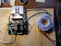
Given that I will have time waiting for the enclosure to arrive I set about building the amplifier boards and the two SLB boards as well as getting an Antek AS2224 200VA dual 24 volt toroid. I chose the 200VA size because there is a reasonable chance that two of them can fit in the enclosure, where bigger ones, e.g., 300VA units, will not.
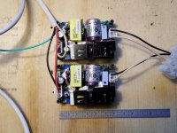
I also considered the use of a SMPS, and what appears to fill the bill is a nice and compact medical grade unit Meanwell makes I happen to have for use in an LM3886 based amplifier I'm working on from time to time. The unit is a 120W, 27V switcher. The plan would be to use two of them per channel.
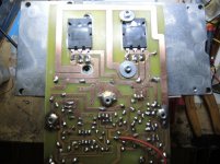
Both amplifier channels have been built and turned on using a good sized passive heat sink I happen to have. Both units behaved exactly the same. 1.6A bias current and -22millivolts output offset with an 8 ohm load, input shorted.
The SMPS setup has perhaps 20 millivolts of switching noise on the output
that can likely be reduced with a modest LC filter. What did impress me was that they run cool and they are tiny. I measured the temperature to be a bit over 40 C when they were powering the amp for more than an hour. The amp heatsink on the other hand was about 58C. I was able to drive the amp to full power out of just under 40 watts with this setup.
Apart from more space and weight the SLB based power did much the same. The AC in from the transformer measured 24.1 volts under load and produced +/-28.3V rail voltages. The noise present on the output was significantly lower than when using the switchers, on the order of maybe 3 or 4 millivolts.
The next step will be when the casework comes in.
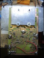
I have attached photos of the amp board attached to the heatsink, the pair of SMPS supplies connected, the power supply setup using the SLB and toroid, and the 1 KHz sinewave full power output into 8 ohms.
PS, I appear to be having problems uploading the photos. I'll try again later.
I have been asked to build an Audio Nirvana amplifier for a client. I acquired the boards from the XRKAudio Etsy shop like many of you as well as SLB power supply boards and the handy RTR speaker protection modules. Next on the list, of course, was a nice sized parts order.
Then the client chose an enclosure from a Pacific Rim source.
I'm now faced with the issue of whether or not the chassis will hold two AN modules, two SLB supplies for dual mono operation, and two toroid transformers, not to mention whether, or not, the case will have sufficient cooling.
Given that I will have time waiting for the enclosure to arrive I set about building the amplifier boards and the two SLB boards as well as getting an Antek AS2224 200VA dual 24 volt toroid. I chose the 200VA size because there is a reasonable chance that two of them can fit in the enclosure, where bigger ones, e.g., 300VA units, will not.
I also considered the use of a SMPS, and what appears to fill the bill is a nice and compact medical grade unit Meanwell makes I happen to have for use in an LM3886 based amplifier I'm working on from time to time. The unit is a 120W, 27V switcher. The plan would be to use two of them per channel.
Both amplifier channels have been built and turned on using a good sized passive heat sink I happen to have. Both units behaved exactly the same. 1.6A bias current and -22millivolts output offset with an 8 ohm load, input shorted.
The SMPS setup has perhaps 20 millivolts of switching noise on the output
that can likely be reduced with a modest LC filter. What did impress me was that they run cool and they are tiny. I measured the temperature to be a bit over 40 C when they were powering the amp for more than an hour. The amp heatsink on the other hand was about 58C. I was able to drive the amp to full power out of just under 40 watts with this setup.
Apart from more space and weight the SLB based power did much the same. The AC in from the transformer measured 24.1 volts under load and produced +/-28.3V rail voltages. The noise present on the output was significantly lower than when using the switchers, on the order of maybe 3 or 4 millivolts.
The next step will be when the casework comes in.
I have attached photos of the amp board attached to the heatsink, the pair of SMPS supplies connected, the power supply setup using the SLB and toroid, and the 1 KHz sinewave full power output into 8 ohms.
PS, I appear to be having problems uploading the photos. I'll try again later.
Last edited:
I wonder how the will hold up over time... I love the small footprint. One thing that bothers me is the size of some cases... Especially, if you are going to actively cool something... at that point the heat-sink doesn't determine the size of the cases needed.
What sort of ripple at 2A, Jan?
Will that cope with a large cap bank at the output?
I have a few 12V MeanWell smps and they are very nicely built, and very reliable.
HD
Will that cope with a large cap bank at the output?
I have a few 12V MeanWell smps and they are very nicely built, and very reliable.
HD
Hi Hugh,
As with almost any SMPS they don't do well with high value capacitance. The 220uF line capacitance from the AN isn't a problem, though. These particular supplies are spec'ed to 100mV ripple at full load. I measured about 20mV at a 1.6A load and that could likely be reduced using some LC filtering between the supply output and the AN.
@thompsontechs,
I would expect these supplies to be reliable and the least of the issues when getting all this into a passively cooled chassis. I will cross that bridge when the candidate chassis is in hand.
Thank you for running all the different ways to power an AN. The little MW SMPS's look very promising for a lowost, compact and lighweight Class A amp. So four of these would be needed for a stereo amp.

Thank you for running all the different ways to power an AN. The little MW SMPS's look very promising for a lowost, compact and lighweight Class A amp. So four of these would be needed for a stereo amp.
Ya, for those that want to give it a listen and limit the budget, these type posts are of great interest. I have a friend that just loves the AN, but he is of limited means, or someone just frugal. I'll build it for him, but my means are slim as well, so this kind of post is welcome.
JT
Well I've finished a major task in the assembly of my 2nd AN 4R - drilling all the holes in the bottom panel!! 😀
I counted 37 holes - 37 various-sized holes that:
a) need to be carefully measured, in terms of positioning
b) then drilled, and
c) then chamfered either side - using a much bigger drill bit - to remove any scarf round the hole. 🙁
All the PCB soldering is done - so it's now "just" a matter of assembly ... followed by making 40 bloody wiring connections! 🙁
Andy
The Waz to cope with this is
I finished proper PSU for AN - I cased two HP 230W laptop bricks, so I'm playing it right now.
Still excellent sound 🙂
I did more temperature measurements, and I have one observation:
---------
I have done that before but mine claimed up to almost 100C while the back on the heat-sink was at 75..
I tried many countermeasures but to no big avail. Unless I used the Active Cooling heat-sinks and now temp is definitely down on the front of the Transistor..You will also need some heat-sink compound between the plastic and the Aluminum plate..BTW this is 5mm thick
Look at the pictures, this also can be done with regular Heat-sinks.
here I use a Sandwich configuration and the Screws are Spring Loaded- so it will keep the pressure always steady on the transistors..Those Sinks I have taken from a G5 Apple Computer as well as the Case. I buy them Cheap and then use them as Amplifier box.. Needs a bit work but in the end it looks good and is all Aluminum.
Regards
Attachments
- Home
- Amplifiers
- Solid State
- Alpha Nirvana 39w 8ohm Class A Amp