The J2 will drive the Tektons to almost a 90db before it starts to give up. Speakers are are easy to drive at 98db efficient.
Could you describe more accurately what's going on?
With 98 db efficient speakers and 90db SPL any amp would work far below 1 watt of output power; a J2 starting to give up at that level does not make sense.
Hi Anand,
I would go straight for the Nirvana with FQA mosfets.
From what Hugh And X have reported the Nirvana is an upgrade to the Alpha20.
When simulating in LTspice both the Alpha and the Nirvana, I see that the Nirvana is better,
it has a higher damping factor, reacts better to 4R loads (lower distortion) and clips at higher voltage.
I've used two Toroidy transformers of each 400VA and 2x18v, my rails after the LT4320 bridge are stable at 25.2VDC, with SLB you need higher voltage specified transformers.
Grts,
Danny
I’ll consider it then.
If anybody needs a pair of Alpha 20 boards, contact me.
Best,
Anand.
Sorry, I never took photos of the other side.
NP, X! 🙂
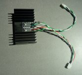
Not much to say other that the wires are soldered onto the pads directly for the lowest profile connection to allow a clamp if needed.
Aah, OK.
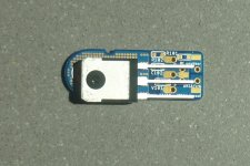
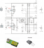
So - Q1: - the 4 holes (in a square) on the RH end of the Snubber board (see below pic) are for soldering the 3 wires which connect to the 3 pins of the MOSFETs?
https://www.diyaudio.com/forums/attachment.php?attachmentid=823825&stc=1&d=1583807075
Q2: Am I right in thinking that:
* the 2 holes on the LHS of the square are both for pin2 (Drain)
* the top right hole is for pin1 (Gate), and
* the bottom right hole is for pin3 (Source)?
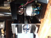
Here they are clamped to that really compact Dell CPU cooler (which, btw, Vunce has verified has no problem cooling 150w thermal load):
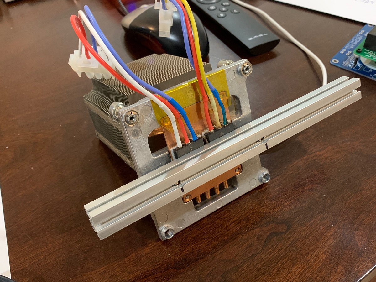
Yes, I had done the same thing with my SLB transistors (which are bolted to a heatsink).
See here:
https://www.diyaudio.com/forums/attachment.php?attachmentid=823827&stc=1&d=1583808373
Incidentally, I find it amusing that the supply transistors in the SLB are in much bigger package than the TO-3P which the AN MOSFETs come in! 😀
Andy
Attachments
Last edited:
As an addendum to my last post, testing continuity on some of my Snubber boards:
1. Yes, I get continuity between the 2 holes on the LHS of the square and pin2 (Drain)
2. I get continuity between the bottom right hole and pin3 (Source)
3. but I do not get continuity between the top right hole and pin1 (Gate)!
But, interestingly enough, I do get continuity between the rectangular pad in the top right corner of the Snubber board and pin1.
Shall I just drill a hole in this and use it for the wire for pin1?
Andy
Hi Andy,
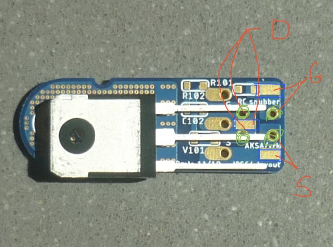
If you look at the snubber board, you won’t get continuity between pin 1 and the rectangular pad on the corner unless the gate stopper resistor R101 is installed. Have you installed the resistor yet? You also need to install the C102 220pF and R102 47R snubber parts on the other locations. Plus the 12v zener diode V101. Pay careful attention to orientation of diode for N or P channel.
Please see markup of your photo. Green circles are holes for the Molex Minifit connector for 90deg connection to the MOSFET snubber board.
Blue rectangles are for parallel direct solder to the snubber like I did.
Red shoes G D S pin locations and corresponding pads.
Attachments

AN Update
Update on AN.
Okay, we have been talking about my first channel mono, not driving my very efficient 8ohm speakers to good sound volume without issue.
Long story short, I found the issue and it was NOT with the Alpha Nirvana.
I decided to hook up the finished AN, again, but I have been meaning to replace some older speaker wires. I fired it up and all was fine at low volume, but started have issues as the power went up.
I decided to change out the speaker cable and try again. In the process I found a cable that had been chewed by a mouse critter. My only guess is that the lower power of the J2 didn't show the flaw as the AN did. Also, I normally don't run the J2 that high anyway, I was in test mode so I ramped it up higher then I normally listen which showed the flaw in the cable.
Okay, problem solved, new cable great sound... still will hold any thoughts and finish up the second mono. It's pretty close now, will get back to you all when I have it up and running with both channels.
JT
JT,
Good to know that the problem was identified. As Inspector Inspector Clouseau would have said, "The case is solv-ed". 🙂
Good to know that the problem was identified. As Inspector Inspector Clouseau would have said, "The case is solv-ed". 🙂
Great news JT. I pulled my hair out for 5 days debugging a new headphone amp design with Hugh once. Signal kept clipping on the O-scope. But when I hooked up a headphone it sounded great. So guess what, it was a bad coaxial cable that had shorted somewhere along the length. Clipping since impedance was close to 0ohms!
Moral of the story: always check your signal cables! I think Vunce has a similar story about spring loaded test lead clips...
As long as you are getting new cables: it makes a big difference on bass authority to use 12ga flexible stranded speaker cables. Not fancy audiophile $$$ stuff, just basic ones on Amazon with banana jacks for $16ea. I measured a big improvement in DF vs the ever popular 16ga copper zip cord.
You can measure it and hear it definitely.
Here is what I use:
Mediabridge 12AWG Ultra Series Speaker Cable w/Dual Gold Plated Banana Tips (6 Feet) - CL2 Rated - High Strand Count Copper (OFC) Construction - Black [New & Improved Version] (Part# SWT-12B-06B) https://www.amazon.com/dp/B01CYGMD4I/ref=cm_sw_r_cp_api_i_0s7zEbV28XPNX
Last edited:
It's alive! I knew it would be okay though because I subbed in all the parts in the other mono while I was waiting for the case to get here... 🙂 I have to head out to the machine shot to fix the niggle on the front plate, do some carbon fiber work, leds in front panel and put covers on. Looks to be done tomorrow or Thursday latest.
I had some Belden 5T00UP 10AWG laying around, so I subbed that in. I've had the one channel of the AN running four a few hours. I put a small fan blowing across it. My dedicated room has this built into the walls, and she runs at 34C lol that's on a sink that is 6x12.
I had some Belden 5T00UP 10AWG laying around, so I subbed that in. I've had the one channel of the AN running four a few hours. I put a small fan blowing across it. My dedicated room has this built into the walls, and she runs at 34C lol that's on a sink that is 6x12.
Last edited:
I made a little drawing to help me mount the outputs of my ANs.
Maybe it can help other diyers.
Cheers,
Jacques
I did the same on a print....


Congratulations, JT, you built an AN real quick, hats off........
And fixed the mouse critter on the cables!!
Now you can listen to this amp. You should be very pleased with the sound quality.
And Andy is coming along nicely too, I know his amp will be special too because of his assembly.
Cheers,
Hugh
And fixed the mouse critter on the cables!!
Now you can listen to this amp. You should be very pleased with the sound quality.
And Andy is coming along nicely too, I know his amp will be special too because of his assembly.
Cheers,
Hugh
Congratulations, JT, you built an AN real quick, hats off........
Indeed - in a day or two, I seem to remember. Contrasting severely with my slow progress. I reckon it will be 4 weeks elapsed before I finish the 4x SLBs alone!
Can't get onto the AN boards until my "pencil air (soldering) gun" arrives. 🙁
And Andy is coming along nicely too, I know his amp will be special too because of his assembly.
I fully expect the 2x stereo AN 4Rs will sound marvelous on my Maggie mids & ribbons, Hugh. 🙂
Andy
Hi Andy,
If you look at the snubber board, you won’t get continuity between pin 1 and the rectangular pad on the corner unless the gate stopper resistor R101 is installed. Have you installed the resistor yet? You also need to install the C102 220pF and R102 47R snubber parts on the other locations. Plus the 12v zener diode V101. Pay careful attention to orientation of diode for N or P channel.
Please see markup of your photo. Green circles are holes for the Molex Minifit connector for 90deg connection to the MOSFET snubber board.
Blue rectangles are for parallel direct solder to the snubber like I did.
Red shows G D S pin locations and corresponding pads.
Thanks, X - of course ... silly me, I had forgotten about that 100ohm gate stopper resistor! 😱
Not sure at this stage whether I will use those 4 holes for a Molex connector ... or solder the wires direct. As they'll be a Molex connector on the AN PCB end ... maybe one at each end of the wires is not a good idea?
Andy
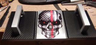
Red Skull (Right Channel)
About all that's left is to solder in the LEDs for the eyes and bolt all the covers.
The blue skull will be left channel and Red for right.
I have the M2X build done too, but haven't sourced a case. After that, it on to fishing!
About all that's left is to solder in the LEDs for the eyes and bolt all the covers.
The blue skull will be left channel and Red for right.
I have the M2X build done too, but haven't sourced a case. After that, it on to fishing!
Attachments
- Home
- Amplifiers
- Solid State
- Alpha Nirvana 39w 8ohm Class A Amp