Today I finally changed the 820Ω carbon resistor in the gain with the 1.8kΩ carbon also.
And yes, I will really stay as is. Everything sounds better, voices and instruments.Without any sign of harshness, with enough detail in the voices, especially at high volume.
PSU +/-21.5V at 2.6A bias version 4R.
Thank you danny _66.
And yes, I will really stay as is. Everything sounds better, voices and instruments.Without any sign of harshness, with enough detail in the voices, especially at high volume.
PSU +/-21.5V at 2.6A bias version 4R.
Thank you danny _66.
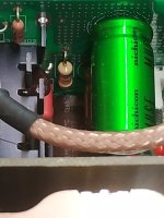
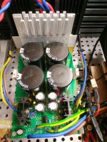
Attachments
Last edited:

Hi Nikos, when you say carbon, you mean carbon film?
And what kind of resistor did you have before?
Regards
And what kind of resistor did you have before?
Regards
Yes carbon film....and before carbon film alsoHi Nikos, when you say carbon, you mean carbon film?
And what kind of resistor did you have before?
https://gr.mouser.com/ProductDetail/YAGEO/CFR-50JB-52-1K8?qs=oypCK0zG326lEhnh6qHf%2Bg==
10uF?Hi,
the one with the lowest voltage because those are the smallest, the others get way too big for 5.6-10uf.
The higher voltage ones use a thicker foil and that's not needed for a line level input capacitor.
For my Alpha Nirvana I used the ClarityCap PUR 250Vdc, they're also very good.
Hi. Is it ok to replace carbon composite resistors with carbon film? Maybe there is a better alternative?
Hi, take a look at this post:
Hi Francois G,
Regarding R124, R126, R133, R135
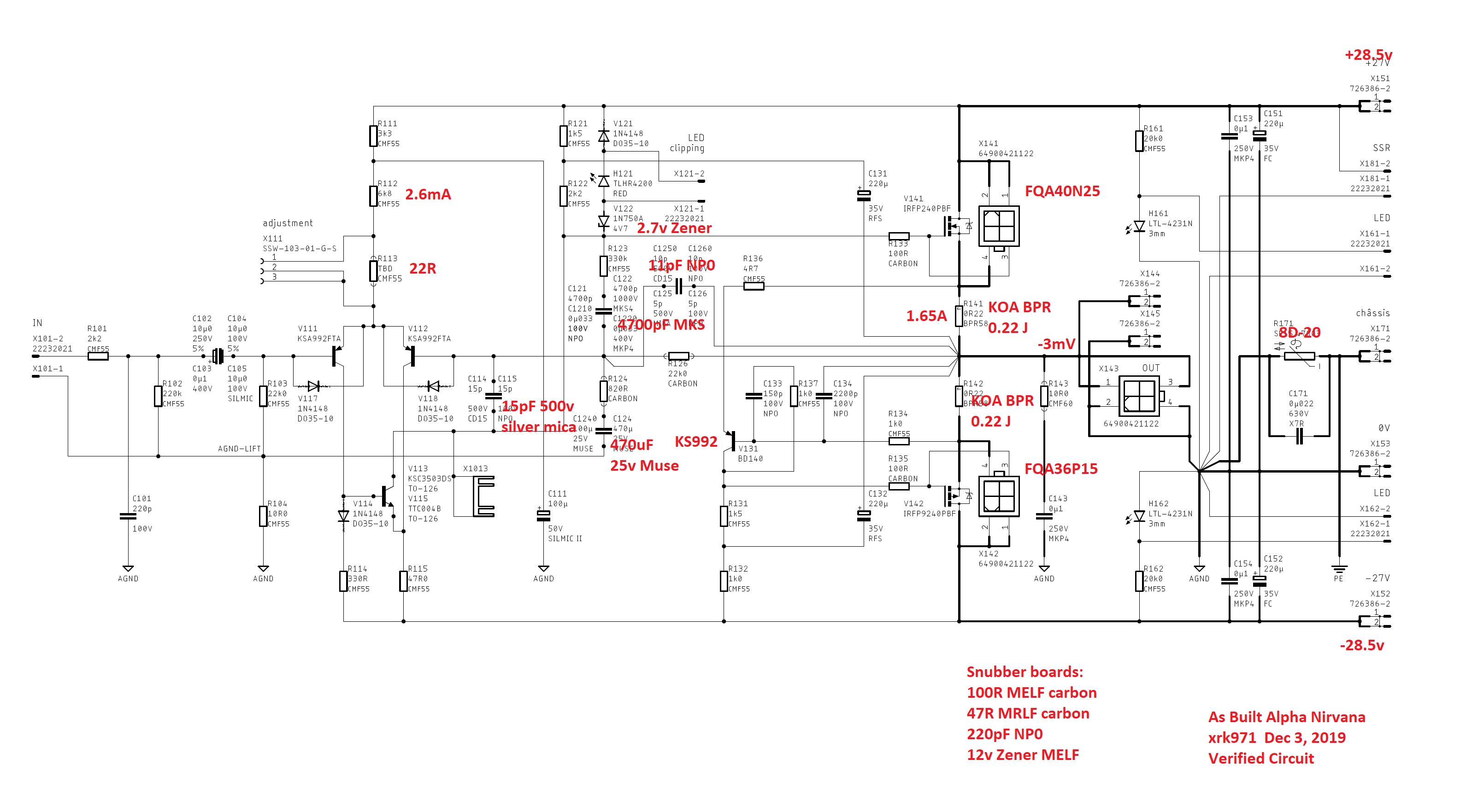
Here is my opinion:
If you use high quality 1% metal thin film on all of these, your amp will sound fine and dandy.
If you believe that having a slightly better redistribution of higher 2nd order harmonic distortion vs third order is something you want (we are talking maybe 2-3dB difference), then change R126 to carbon film. But not carbon composition. They don't come better than 5% so...
Regarding R124, R126, R133, R135
Here is my opinion:
If you use high quality 1% metal thin film on all of these, your amp will sound fine and dandy.
If you believe that having a slightly better redistribution of higher 2nd order harmonic distortion vs third order is something you want (we are talking maybe 2-3dB difference), then change R126 to carbon film. But not carbon composition. They don't come better than 5% so...
I could use some help here as I am trying to place my parts order, and am hoping to keep things within 2 suppliers. Mouser and Parts Connexion have almost everything I need other that the KOA Speer BPR58CR22J, which was preloaded in the BOM cart for Mouser for R141/142, and is currently backordered. Can anyone recommend a suitable replacement at either of my preferred suppliers?R141 and R142 have been discussed previously in this thread (first 10-15 pages where X did a multitude of measurements and experiments). These are the source resistors for the output stage MOSFETS. They do have an influence on overall sound and distortion. In these positions I am still experimenting but I have chosen Riedon FPR2 series which have a copper magnanin foil that is seen in some expensive resistors of the Vishay VPG division. Values here can be 0.18 ohms to 0.25 ohms. Of course at lower values, bias current is higher and vice versa. At 0.25 ohms, my bias current is ~ 1.35A. I plan on trying 0.22 ohms in the future but the only value that was in stock at the time of purchase was 0.25 ohms.
EDIT: I think this should work! https://www.mouser.com/ProductDetail/KOA-Speer/BPR58CFR22J?qs=1He0yLMpldCZL5xQ2oQYLQ==
Last edited:
Gthibodeaux,
You can look at this one: BPR58CFR22J.
My understanding is that this SKU has a kink in the leads, where as the BPR58CR22J has straight leads.
You can look at this one: BPR58CFR22J.
My understanding is that this SKU has a kink in the leads, where as the BPR58CR22J has straight leads.
Can someone please explain this to me like I'm 5?! I'm in the process of ordering parts, and have chosen a Panasonic FM Series 470k 25v cap for C124, and came across this post. I'm not really familiar with the concept of bypass capacitors, and in trying to do some research I just got more confused as there is SO MUCH information across many different specific categories that I just got more confused than helped... at the end of the day I just want to know how exactly i might do this, and maybe get some additional information on any specific recommendations for the 2.2uF MKP caps... Sorry for the N00B questions, but I'm trying to learn!You can add a high quality film cap to bypass C124 like 2.2uF MKP.
Because bypass capacitors reduce noise and stabilize the power to the design. Audio amplifiers achieve reduced distortion and improved audio quality.
Add in parallel a small film capacitor across a much larger value electrolytic cap. Larger capacitors tend to have higher inductance and dielectric absorption affecting higher frequencies the most. Bypassing with smaller capacitor (creating alternative path at high frequency) improves overall performance. It also allows to use cheaper main capacitor for cost reduction. Huge electrolytic caps (with higher inductance) in power supply seems to be ideal target for bypassing (speaker current closes thru them), but low ESR bypassing caps in parallel with inductance of main caps can create parallel resonant circuit.
I suggest to follow the standard schematic if You're doing it for the first time 🙂
👍I suggest to follow the standard schematic if You're doing it for the first time 🙂
Best,
Anand.
Thank you! This is very helpful.Because bypass capacitors reduce noise and stabilize the power to the design. Audio amplifiers achieve reduced distortion and improved audio quality.
Add in parallel a small film capacitor across a much larger value electrolytic cap. Larger capacitors tend to have higher inductance and dielectric absorption affecting higher frequencies the most. Bypassing with smaller capacitor (creating alternative path at high frequency) improves overall performance. It also allows to use cheaper main capacitor for cost reduction. Huge electrolytic caps (with higher inductance) in power supply seems to be ideal target for bypassing (speaker current closes thru them), but low ESR bypassing caps in parallel with inductance of main caps can create parallel resonant circuit.
I suggest to follow the standard schematic if You're doing it for the first time 🙂
Okay, am I crazy, or is the BOM incorrect for these components? R101 as 2k2 and R102 as 220K
In several posts across the forum, and from what I'm seeing on the schematic the values are R101 - 100R, and R102 - 47R
Is there something I'm misunderstanding?
In several posts across the forum, and from what I'm seeing on the schematic the values are R101 - 100R, and R102 - 47R
Is there something I'm misunderstanding?
@Gthibodeaux , If you are going to make statements like you have above, please attach or quote the image or words and where you found this information. I have spent about 1/2 hour looking at various schematics posted trying to help you, and the schematic above in post #3707 is the one that I would use.
Cheers,
MM
Cheers,
MM
I am seeing in the Mouser cart 2 MELF caps that are marked R1001 (100R) & R1002 (47R), which I'm guessing are the snubber components. That said, I guess I just don't know if the R101 & R102 resistors listed in the BOM are erroneous and should be ignored, or have been mislabeled and belong somewhere else on the boards...
I was going to mention that you may have been getting confused with the resistors for the snubber boards. The R101 and R102 resistors are needed on the AN39 amplifier board and are not erroneous
MM
MM
Hi guys. My output offset voltage is -2mV without speakers. When I connect speakers it goes up to 34mV. Is this how it should be or is there something wrong?
Hi guys. My output offset voltage is -2mV without speakers. When I connect speakers it goes up to 34mV. Is this how it should be or is there something wrong?
What a very interesting discovery.
I only have ever measured (and adjusted) DC offset with no spkrs attached ... so I can't help you. 🙁 (You're obviously higher up the OCD scale than I am! 😀 )
@Hugh?
Last edited:
- Home
- Amplifiers
- Solid State
- Alpha Nirvana 39w 8ohm Class A Amp