@Nikos I have 20V rails, 2.2A bias. I don't have a scope but ripple was sub 5mV on my Fluke. You can dial out as much as you want, the trade off is dissipation and voltage drop.
There's 22,000uF on the input of each rail of the cap mx, you don't need much on the output because of the multiplier. My AN39 is built dual mono.
I have Shottkys in the bridges, and a small aluminum plate is easily enough to keep them cool. There are pictures in this thread of my build. Just search the thread for posts from me.

@simon dart
Thank you for your response.
Two more small questions since this multiplier seems to be quite economical in relation to SLB. What value in volts of transformer did you use to achieve 20 volts at the output and
Which part Shottky code did you put in as rectifiers.
Thanks again.
Thank you for your response.
Two more small questions since this multiplier seems to be quite economical in relation to SLB. What value in volts of transformer did you use to achieve 20 volts at the output and
Which part Shottky code did you put in as rectifiers.
Thanks again.
Attachments

Yes there's a little less drop across the Gtose Johnson multiplier than with the FETs in the SLB. I got a transformer custom wound with four secondaries 17.5V in case I preferred a CRC or CLC topology. The CapMx won the very unscientific audition! There are 4 bridges of STPS20SM60 diodes.
Can you explain with few words that?The CapMx won the very unscientific audition!
Those diodes have very low Vf 0.37V
....very good
I have the same trafo 2X18 V.
i will land i think at 20 volts
Thanks.
Last edited:
@alexya

I believe this can be done. If your rail voltages are at +/-35V, then you'll have to trim the resistors that are supplying the differential input pair, so that you can target about 2-2.5mA (so adjust R112 or R113, etc...). The design was set for +/- 27 to 29V rails.
But the bigger problem is the dramatically increased dissipation for the output MOSFETs. We are now talking about 35*2*1.7A = 120 watts of dissipation per channel. If you have huge heatsinks, no problem. If you have moderate sized heatsinks along with a fan, no problem. I personally don't like heatsink temps to be higher than 55 deg C. The output MOSFETs chosen for this design (FQA versions) are very robust so they can handle the increased dissipation (I would still double check the datasheets). If you choose a lower current setting, i.e. 1.5A or lower (change R141, R142), it will affect what you can use as a 4 ohm load but 8 ohm loads are still fine, provided they are efficient speakers. 1.7A will give you 3.4A peak.
Up to you to decide. Realize this is a single ended Class A topology, so no shifting to Class B. The amp will just clip when it has ran out of current to supply to the load.
Best,
Anand.
But the bigger problem is the dramatically increased dissipation for the output MOSFETs. We are now talking about 35*2*1.7A = 120 watts of dissipation per channel. If you have huge heatsinks, no problem.
That's the same as my 4R builds, Anand. 👍 (3a x 21 x 2 = 126w, each channel.) And yes, they certainly get warm - even with a 200x300 heatsink for each channel.
But, @alexya , I would suspect that whilst you'll get over 60w output from those DC rails ... the amp will like 4 ohm loads even less than the 'standard' 8R version does! 😵
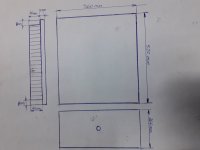
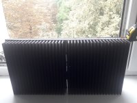
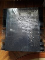
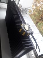
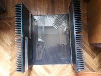
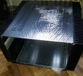
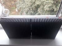
Now I am in the construction of the case, I think that these radiators are more than acceptable that I have, to feed the amplifier at
+/-35V, what do you say?
+/-35V, what do you say?
Attachments
-
 111111.jpg213.8 KB · Views: 120
 -
 AAaomw9.jpg236.1 KB · Views: 115
 -
 ArLi9Qx.jpg360.1 KB · Views: 132
 -
 cpoSuky.jpg518.2 KB · Views: 107
 -
 IhMEECC.jpg473.6 KB · Views: 115
 -
 JS4Qbr3.jpg505.5 KB · Views: 110
 -
 lSEQxMR.jpg281.6 KB · Views: 101
 -
 MJUeqOr.jpg394.9 KB · Views: 106
 -
 mYzu3SC.jpg639.9 KB · Views: 99
 -
 PR1YD1y.jpg215.2 KB · Views: 115
 -
 WiTjzck.jpg358.7 KB · Views: 114
 -
 YZL2O9y.jpg237.8 KB · Views: 114
I will use two transformers like this,,,,,,,,,,,,,,,,,
https://www.tme.eu/ro/details/55183-p1s2/transformatoare-toroidale/talema/
https://www.tme.eu/ro/details/55183-p1s2/transformatoare-toroidale/talema/
Chassis looks like the size of a Modushop 5U/500, maybe a little bigger with the more prodigious heatsinks. Lots of space and heatsinks are great for 120W dissipation/ch, you can probably try even higher. I would center the Alpha Nirvana board in between the two heatsinks so each MOSFET has a dedicated sink. Look at post 2228 for inspiration. Note the builder used the Mosfet snubber board and placed the Mosfets at roughly 1/3rd vertical distance from the bottom for best convection.Now I am in the construction of the case, I think that these radiators are more than acceptable that I have, to feed the amplifier at
+/-35V, what do you say?
With 25V secondaries, you will probably be under +/-35V when loaded using conventional rectifiers, but that’s fine.
Best,
Anand.
Last edited:
Now I am in the construction of the case, I think that these radiators are more than acceptable that I have, to feed the amplifier at
+/-35V, what do you say?
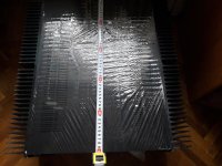
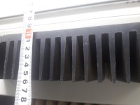
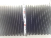
TMI - just give us the dimensions of each channel's heatsink!
He did, just look at the pics and the drawing.TMI - just give us the dimensions of each channel's heatsink!
55mm thick, 510 mm long and about 250mm tall. That’s the total for a pair of heatsinks on each side.
Best,
Anand.
He did, just look at the pics and the drawing.
As I said, Anand - for me ... no pics ... just dimensions. That immediately passes on the info to me. (Sure, I understand other people like pics rather than words.)
alexya,
Have you already got the transformers?
500 VA per channel is not required - 300 VA per channel or even a single 500 VA unit with 4 secondaries will be good enough (this probably will have to be custom, as I have not seen off the shelf transformers with 4 secondary voltage taps).
Are you in Europe? There are other choices too, specially for custom voltage that can bring you closer to +/28V or around that.
General rule of thumb is to take the total dissipation (for example 120W/ch * 2) and select a transformer VA that is 2X's to 3X's for optimum balance between price, longevity and heat. That means 500VA to 750VA total is fine.
Toroidy is a nice brand, particularly for Europe and that would be my recommendation.
I used an 800VA in my NPXP build but that allows me to utilize different designs of higher or lower bias currents as I am willing.
Best,
Anand.
Toroidy is a nice brand, particularly for Europe and that would be my recommendation.
I used an 800VA in my NPXP build but that allows me to utilize different designs of higher or lower bias currents as I am willing.
Best,
Anand.
Yes, I am from Europe, I have these 500VA transformers, it would be a shame not to build this amplifier with them, I will use a scheme of RCRCRC,this way the 35Vdc voltage will drop a little more
Even with a simple CRC your voltage under load will be approximately 32-33V.
As Anand mentioned, your chassis heatsinks will handle that without a problem. 👍🏻
As Anand mentioned, your chassis heatsinks will handle that without a problem. 👍🏻
Thanks Anand.
If you choose 32V rail over the nominal 27V and to achieve optimal power output into 8R you should increase quiescent to 1.7*32/27=3A.
This will dissipate 3*64=192W PER CHANNEL but the benefit will be 56W of glorious Class A. But you better be ready for heavy duty waste heat and in my view you will require liquid cooling.....
Hugh
Last edited:
- Home
- Amplifiers
- Solid State
- Alpha Nirvana 39w 8ohm Class A Amp