@jimk04 and others,
Back in 2020 Hugh explained it rather well in another thread (reference the schematic below):

It’s important to understand this as it is very similar to the way the Aleph J (and all other precursors to the Aleph J, such as Aleph 30, 60, 2, etc…) works. The big difference is in the DESIGN of the output stage current source in the Alpha Nirvana. It’s even more efficient and is based on a P-Mosfet that is controlled by a PNP transistor. You will realize that this amp really should be called the Aksa Lender Nirvana. Moreover, the damping factor of this amp is much much higher than any “low wattage” SE Class A design (whether tube or solid state I’ve heard). Sonically it isn’t as syrupy sounding in the midrange but does provide enough of that ‘magic’ without losing midbass and bass control. I hope someday(!) to return to this design and change the active N-channel MOSFET to a JFET SemiSouth!
Have fun building it!
Best,
Anand.
Back in 2020 Hugh explained it rather well in another thread (reference the schematic below):
With V131 in place (that is, set up as an active current flip-flop across the two output device currents), then:
At pos half cycle, upper device (V141) controls voltage AND current into the load, and
At neg half cycle, upper device controls voltage BUT NOT current into the load, this load current is directed by the lower device (V142) alone, which never turns off and never controls voltage (signal).
From this odd combination of different control of the signal with two outputs, we can see that the upper device/V141 is the sole device controlling voltage through the entire waveform. This MUST happen only if all devices DO NOT TURN OFF. The upper 'voltage defining' device does not control current in the negative half cycle, however; this is passed to the lower device, but this lower device does NOT turn off. Neither does the lower device EVER control voltage at the load at any point of the waveform.
Because the total control of the voltage at the load is devolved to the upper device, in this sense this is regarded as single ended control, as though only one device were controlling the entire waveform.
This is almost a semantic difference, but it is significant, because at the entire negative half cycle, the lower device controls load current. It is true this control is tightly controlled by the constant on upper device which forces voltage control at all times, but it can be viewed as Single Ended.
The correct term, however, attributes more correct reality with the phrase, SINGLE ENDED PUSH PULL.
This is a very interesting mind puzzle because with very simple circuits we can run into serious difficulties describing precisely what is happening, particularly when we are using terms from the past.
HD
It’s important to understand this as it is very similar to the way the Aleph J (and all other precursors to the Aleph J, such as Aleph 30, 60, 2, etc…) works. The big difference is in the DESIGN of the output stage current source in the Alpha Nirvana. It’s even more efficient and is based on a P-Mosfet that is controlled by a PNP transistor. You will realize that this amp really should be called the Aksa Lender Nirvana. Moreover, the damping factor of this amp is much much higher than any “low wattage” SE Class A design (whether tube or solid state I’ve heard). Sonically it isn’t as syrupy sounding in the midrange but does provide enough of that ‘magic’ without losing midbass and bass control. I hope someday(!) to return to this design and change the active N-channel MOSFET to a JFET SemiSouth!
Have fun building it!
Best,
Anand.
Last edited:

Hugh it is the best sounding amp. I listen all day with this amp, never tire.thanks again.
I wonder how many other parts would need be tweaked to change the
N channel to Jfet semisouth on Nirvana as Anand Mentioned in above post?
I have been curious myself.
Scott
N channel to Jfet semisouth on Nirvana as Anand Mentioned in above post?
I have been curious myself.
Scott
@bigaudioscotto
Read posts 2363-2370.
I imagine the amp will become even more detailed and that may/may not be what you want.
Best,
Anand.
Read posts 2363-2370.
I imagine the amp will become even more detailed and that may/may not be what you want.
Best,
Anand.
Regarding gatestopper.
The BOM calls for a MELF 100r Carbon to be populated on the snubber board. I can't find any SMD carbon resistors so I must be looking up the wrong terms. Do we have a Mouser link at all guys?
The BOM calls for a MELF 100r Carbon to be populated on the snubber board. I can't find any SMD carbon resistors so I must be looking up the wrong terms. Do we have a Mouser link at all guys?
If anyone wants me to arrange a buy of the Excicons from Profusion shout up.! Good price break at 10 off so would'nt need many takers
Hello,Regarding gatestopper.
The BOM calls for a MELF 100r Carbon to be populated on the snubber board. I can't find any SMD carbon resistors so I must be looking up the wrong terms. Do we have a Mouser link at all guys?
Just type the part number and mouser will show you the desired result.
Cheers
Spiros
Attachments
Thanks. I went in from the top and filtered down to MELF but then it didn't give a carbon option!
So Hugh, would this work even though the Exicons are lateral mosfets, instead of a vertical mosfet? Moreover, one needs to be careful about properly connecting the gate, drain and source pins since it is switched on lateral mosfets vs vertical mosfets. The Exicons are certainly very durable devices. More H2 typically means more midrange presence in my experience.Hmmm, Scott how about using a dual-die Exicon in place of the nmos?
Very low transconductance 1.4S vs. 6.9S, so more H2.
No other change to the schematic.......
Hugh
Please share the fruits of your knowledge!
Best,
Anand.
Hugh,Anand
That is exactly what I am looking for more mid range,and more texture the way it is for me is just to dry to clean.
Scott
That is exactly what I am looking for more mid range,and more texture the way it is for me is just to dry to clean.
Scott
Just remember:

Drain is the center pin on a Vertical Mosfet. Source is the center pin on the lateral mosfet. They have to correspond when you fly wire back to the main Alpha Nirvana PCB.
The snubber boards however were designed for vertical mosfets. It might be a messy modification since C102 and R102 (on the snubber board) connect between the drain and gate and the 15V zener is connected between the gate and source (Cathode towards the gate in an N channel). I’ll need to have X and Hugh weigh in on the options and their opinions.
Best,
Anand.
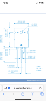
Here is the pin out on the Exicon’s.
Anand makes a good point in above post.
Scott
Anand makes a good point in above post.
Scott
Attachments
Last edited:
I can tell you that C124 is directly in the feedback circuit and will definitely affect the sound. Both in value and in quality of that capacitor. Many will use a non polar capacitor type for best sound, but in this case a minimum value of 100uf is recommended as seen in the schematic. I think it has to do with achieving a low ESR value which larger capacitors such as the 470uf do have compared to 100uf. You can experiment and let us know. My thoughts and experiments are on post 2140.
Best,
Anand.
Best,
Anand.
Anand,
Thanks I have been thinking that C124
Needs some experimenting I will play with some various brands and values and give feedback.
Should the voltage value be higher than that 25v listed on the schematic to at least 35v?
Scott
Thanks I have been thinking that C124
Needs some experimenting I will play with some various brands and values and give feedback.
Should the voltage value be higher than that 25v listed on the schematic to at least 35v?
Scott
25V is fine. This is a low voltage node in the circuit from what I can see.Should the voltage value be higher than that 25v listed on the schematic to at least 35v?
Best,
Anand.
You can add a high quality film cap to bypass C124 like 2.2uF MKP.
- Home
- Amplifiers
- Solid State
- Alpha Nirvana 39w 8ohm Class A Amp