Andy it's in the PASS section of the forum and in the store. A 2 way active XO with adjustable 6, 12, 18 or 24db slopes.
https://www.diyaudio.com/community/threads/diy-biamp-6-24-crossover
Seems my AN build is throwing me swerve balls before I'm out of the blocks! I thought it was good for LF due to the feedback or DF or whatever then it would be suited to bass. Guess I can try, and I do have a class d also.
https://www.diyaudio.com/community/threads/diy-biamp-6-24-crossover
Seems my AN build is throwing me swerve balls before I'm out of the blocks! I thought it was good for LF due to the feedback or DF or whatever then it would be suited to bass. Guess I can try, and I do have a class d also.
Aah, OK, Jim. Sounds like a good unit.
All I mean by my comments ... is that the AN is such a wonderful-sounding amplifier - it would be a waste to put it on bass duty. Also, bass drivers need plenty of grunt - not finesse!
I use an AN 4R on each of my 2-way active mains; these hand over to subs @ 110Hz - which are driven by 800w Class D amps.

@jimk04
Germane to the discussion between you and andyr, please also read my review on post #2222. One of the speakers we used in the comparison was an older Legacy Audio Focus 20/20 loudspeaker. The impedance and phase curves of this speaker are particularly challenging especially in the 50-200Hz area, with a nadir as low as 1.7 ohms and obtuse phase angles:

What is important is how well the AN39 did. In fact, my AN build uses only +/-24V rails, so the power output is even lower than the regular run of the mill version. And it’s biased at ~ 1.5A, so no favors for a 4 ohm load. We didn’t listen at head banging levels, but regularly achieved 85dB at the listening position (about 7-8 feet away, roughly 2.25-2.5 meters).
Whenever you have an impedance and phase curve available (and you all do have it available, especially with a quick measurement using Dayton Audio’s DATS V3 or equivalent), you need to ask yourself how it relates to listening to hifi. Statistically speaking, in 2 ch audio, most of the ’music’ lies in the 50Hz to 5khz area. So I study that area closely, because that is what your power amplifier “sees.” Same assessment is needed when studying the overall sensitivity of the loudspeaker. Of course this is an estimate since it doesn’t take into account what genre of recordings are in your library, etc…
Best,
Anand.
Germane to the discussion between you and andyr, please also read my review on post #2222. One of the speakers we used in the comparison was an older Legacy Audio Focus 20/20 loudspeaker. The impedance and phase curves of this speaker are particularly challenging especially in the 50-200Hz area, with a nadir as low as 1.7 ohms and obtuse phase angles:
What is important is how well the AN39 did. In fact, my AN build uses only +/-24V rails, so the power output is even lower than the regular run of the mill version. And it’s biased at ~ 1.5A, so no favors for a 4 ohm load. We didn’t listen at head banging levels, but regularly achieved 85dB at the listening position (about 7-8 feet away, roughly 2.25-2.5 meters).
Whenever you have an impedance and phase curve available (and you all do have it available, especially with a quick measurement using Dayton Audio’s DATS V3 or equivalent), you need to ask yourself how it relates to listening to hifi. Statistically speaking, in 2 ch audio, most of the ’music’ lies in the 50Hz to 5khz area. So I study that area closely, because that is what your power amplifier “sees.” Same assessment is needed when studying the overall sensitivity of the loudspeaker. Of course this is an estimate since it doesn’t take into account what genre of recordings are in your library, etc…
Best,
Anand.
Hi Anand,Myles,
Using the most current schematic is important for this build, without it, things can get confusing. V113 here is the KSC3503. V115 is the functional equivalent (TTC004B) so you can use that if KSC3503’s are unavailable. V112 is a KSA992.
View attachment 1203127
As I can see in the schematic, the NTC thermistor has changed from 47R (SL15_47003)
Thanks
I have purchased some 7R. Will they be ok for the ground lift?
Thanks
Thanks
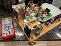
Getting mine built up. First pictures show the main build with the PSU and active cooling. Running a quad output 24VAv 600VA trafob of unknown Ebay origin. Seems fit for purpose. So I have a dual mono type set up using LT4320 and CapMx. Gives me just over 30vdc unloaded and about 28 loaded with 2.5A resistive load (12R 50Watt) ....soon gets hot!


And then the amp section sits on top. Have powered up and seems to be OK but one of the devices seems to get very hot quickly, so I need to look into that. I don't have the remote MOSFET mounting boards and associated snubbery and external gate resistors. I stated to add an additional stopper to one device but I wasn't happy with the outcome so haven't procede with that. Maybe the hot one is oscillating.
Not measured the final loaded PSU voltage. Shall report back.
Hi
Can you give me the info where you get this nice little active rectifier board?
thanks
chris
Can you give me the info where you get this nice little active rectifier board?
thanks
chris
Hi Chris. It's a Prasi board. It's in the big old 4320 ideal rectifier thread. Gerbers are there. I'll see if I can see them for you.
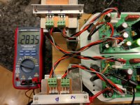
Rails all sag to 28.3v so there isn't any undue load anywhere but one of the P.ch gets instantly hot. I'll maybe swap it for another. I have read somewhere someone struggling with a hot output device and it all measured OK, just got hot.?! Swapped it for another and it was OK. We shall see.
Edit.....for Chris..
https://www.diyaudio.com/community/threads/lt4320-based-active-rectifier.336572/post-5770749
Last edited:
So yes something pretty amiss. I have 22 or so V of output offset! And both channels (L and R) P channel devices get hot fast.
Check all pinouts on the input stage and VAS transistors.
And also the outputs are correct and wired too.
+22V offset tells me the nmos is shorted.
HD
And also the outputs are correct and wired too.
+22V offset tells me the nmos is shorted.
HD
Thanks Hugh. Atleast my mistake seems consistent seeing as both channels behave the same. Will try to get time on it soon.
Jim,
Check orientation of V113/V115 (KSC3503 or TTC004B) with your somewhat unorthodox implementation of the X1013 heatsink. Make sure that V113 isn’t flipped on the board.
Best,
Anand.
Hi Anand thanks for your input. The boards are by another member and I came to the conclusion this morning looking at various photos and the diagrams that I do indeed have V113 backwards I think.
Yes swapped one channels V113 orientation around and all seems good. 5mV offset. Devices nicely warming up and not cooking!
Sorted both channels now and rectified an incorrect rail indicator LED. All working nicely or so I believe.!
Rails all 28.4v +/- 0.05v. DC offsets are 4mv and 5mv with the given red annotations on XRKs schematic. Didn't try or need the pot. Still felt a bit wary of the mosfet temps. On P channel in particular. See photo of 95c case temp. On the metal tab. Tried various measures of it over them all and the hot P probably averages 90c. Other P 60C. N ch1 80c and N.ch2 60C. Both hot ones on same audio channel and heatsink so maybe something to look into. Or just role with it. Air outlet fins are about 36C.
Took some VgS measurements.
N1 4.63v
N2 4.74v
P1 3.31v
P2 3.19v.
The 95C P channel is the 3.19Vgs. I think this tells me it is drawing more current? Should I alter any resistors ? The outputs are FQAs . But otherwise all seems good. Need to rig up the input and speaker connections. Haven't got the fan module temp sensor in yet. Need to extend the wire. Seem fine sat at the low speed it's on.
Attachments

Can you tell us what your bias current is? What is the measurement across R141 or R142? Place one multimeter lead on R126 and the other lead on the source of V141 (Nchannel Mosfet). What value did you use for R141? Use Ohm's law and let us know.
I can't help you too much from a thermal standpoint because your build is somewhat of an experiment. I don't know a thermal model for it compared to standard Modushop heatsinks. I'm sure there are others here who are more knowledgeable! I also do not know if your thermal measurements are accurate.
Best,
Anand.
Anand I appreciate your interest in my project.
R141/2 are 0r22. I'm getting 0.38v across = 1.72A bias. (x 28.4v = 49w)
No I don't know how accurate my temps are either. Using a k-probe which as you know is better than IR but my means to test are probably arbitrary at best! See the screwdriver pressing the probe down!
But the sinks themselves seem cool enough
Last edited:
Re-grease the pmos and reattach with a new mica/ceramic washer with correct torque on the studs.
This might improve the heat transfer; if the sinks are cool it tells me that the transfer is poor.
Looks like the electronics is OK now, good work.
HD
This might improve the heat transfer; if the sinks are cool it tells me that the transfer is poor.
Looks like the electronics is OK now, good work.
HD
- Home
- Amplifiers
- Solid State
- Alpha Nirvana 39w 8ohm Class A Amp