Thorens TEM3200 use Blöhbaum System, it is just a circlotron with local feedback
EP1548934B1 - Fully differential push-pull amplifier
- Google Patents
6moons audio reviews: Thorens TEM 3200
Ahh so, I did this al longer time, have also a all plate follower but is normal amp, sounds fantastic also.
If local feedback is back to first amp cathode resistor what is current feedback by the way.
hi kees52,
do you know how to simulate a wingspread with a circlotron output stage ?
simple push :
http://circlotron.audio/data/simulation/img/wingspreadMosfet.png
http://circlotron.audio/data/simulation/asc/WingspreadMosfet.asc
circlotron :
http://circlotron.audio/data/simulation/img/wingspreadMosfetCirclotron.png
http://circlotron.audio/data/simulation/asc/WingspreadMosfetCirclotron.asc
there is an error somewhere.....
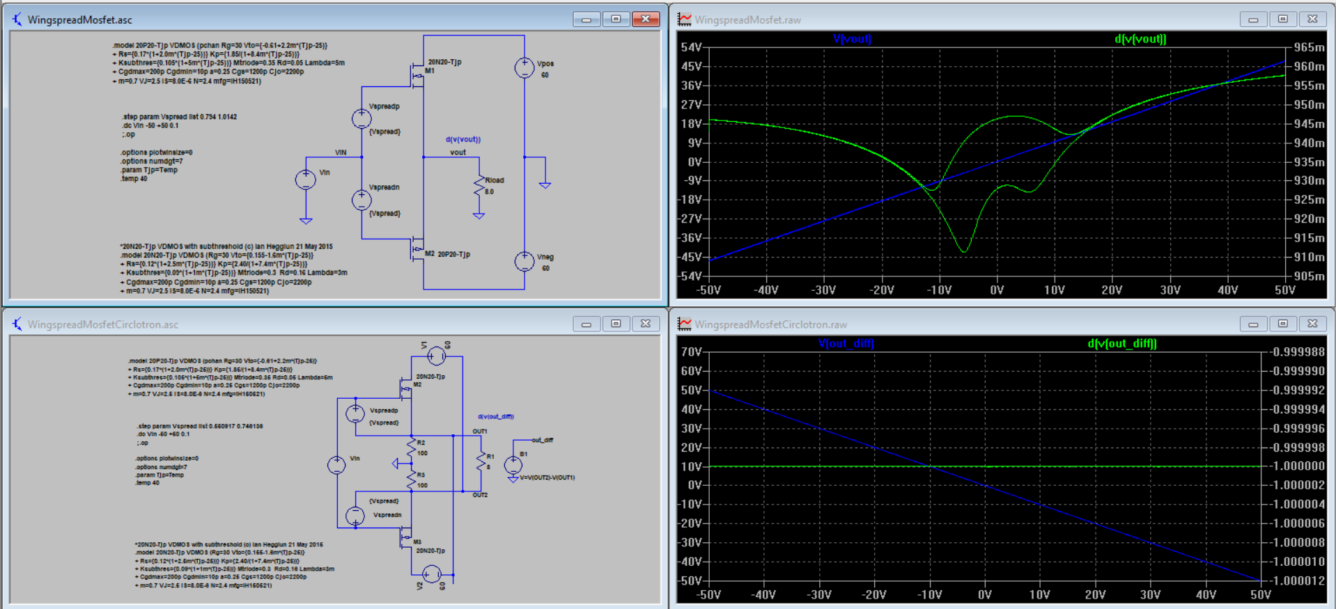
What error in what way?
It seems that DC servo is manual in this schematics? With pots
This is Thorens input stage..
Thorens TEM 3200 clone
Input stage of KES 2sk170 maybe could be replaced with this topology, using global feedback directly to op amps , saving one stage...
Last edited:
What error in what way?
I have the same output if i remove mosfet 🙂
😱I have the same output if i remove mosfet 🙂
I dont understand ? how can you have output without output mosfet ? Can you be more specific what did you do in spice
I have the same output if i remove mosfet 🙂
it must be without gate source on voltage, bjt is 0.6 volts and mosfet special laterals 3.8 or 4 but in sim and if model is not accurate it do can give this results.
You have a voltage vas, so it's voltage can be above output voltage but afcourse you have just max 50 mA.
That is wahy I say about the opamps, with 24 volts on them in real world do output voltage minus 8 volts, 4 for eacht side of amp.
so a njt buffer on a voltage 8 volts higher then rail will do.
Last edited:
Hi All
X ask me to post it here, so I do, some ideas behind it because I have simmed it only, but measures nice. distortion test in 4 and 8 ohm.
Maybe nice for a power J-fet .
regards
HI Kees
The diagram that I would like to try is very similar to this one, double differential and mosfet without driver, but with generators in the 2nd floor I can not polarize the mosfet, how did you do it here ?
I tried to add resistances like the 680 of your schema but it does not work
https://www.diyaudio.com/forums/att...fet-circlotron-screenhunter_1108-21-22-17-jpg
Last edited:
no css version
This one is now allfet
and distortion is even lower, but can als be because of idle current is different.
I did see you have the old version found, because I do not like voltage feedback I did current feedback later making it also not full but local.
regards
Attachments
the problem is not the cascode or the feedback, I would like to replace R17 and R18 with CSS,
as you did on the composite mosfet scheme
but I cant polarize output mosfet
(i dont have bsp126 model)
as you did on the composite mosfet scheme
but I cant polarize output mosfet
(i dont have bsp126 model)
Last edited:
Thanks
Could you upload your lib folder on this link ?
you often have models that I do not have (irf610 now and bzx)
and even if I have them, they are not necessarily the same
Nextcloud circlotron.audio
Could you upload your lib folder on this link ?
you often have models that I do not have (irf610 now and bzx)
and even if I have them, they are not necessarily the same
Nextcloud circlotron.audio
Last edited:
Thanks kees for you lib, i have now same model as you.
I still have very high currents on four mosfets with your file:
Is(M2): 0.0420613
Id(M3): 2.69548
https://www.diyaudio.com/forums/att...45970d1553806186-allfet-circlotron-kaneda-asc
this schematic is dangerous, with only a variation of 1ohm on R2 I go from 2A to 300mA
I still have very high currents on four mosfets with your file:
Is(M2): 0.0420613
Id(M3): 2.69548
https://www.diyaudio.com/forums/att...45970d1553806186-allfet-circlotron-kaneda-asc
this schematic is dangerous, with only a variation of 1ohm on R2 I go from 2A to 300mA
Last edited:
I have set it up for 100 mA idle in output, but when build, I think you have to experiment with the pot and the resistors.
The driver mosfets are on 34 mA here you need class A because how more driver current hpw better the distortion specs, special for IRF240 type mosfet you need even 50/75 mA idle, and cool these drivers, mine are 80 mA with verticals, this because the gate capacitance is high, I have the driver also on the heatsink and that works fine, you have laterals, and I do not now what happens as the drivers are also on that heatsink, just try, otherwise a NTC is needed into the resistor network in idle pot. But try first, and go built it, you will see things are different from simulation, but a good start, the idle pot needs max resistance for start otherwise you get uge idle curent and destroy the fets, I have on sim setup resistors so this is limited and more save.
regards
Attachments
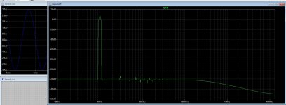
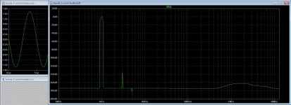
The versions with the current feedback you see clearly the differences with voltage feedback, youn have slightly more distortion but als have a uge bandwidth, current feedback is mine favorite for this, it has not the limitations of voltage feedback, your resisistor network on feedback I do like also, maybe this give a result on the current sources.
The cascode in the Jfet stage is needed as the voltage is higher then max Jfet drain source, so this is always a good idea.
Here the lateral mosfets have 200 mA idle, distortion with almost max swing is -100dB, but because of the current feedback you see down the -100dB more
harmonics, but that is not important as it is so low down the scale.
Idle current has uge impact, see the other -120dB version plot.
regards
Attachments

Last edited:
you can schematize the current fedback ?
do you have open the file in my post 995 ?
Your post 995 has current feedback.
I have optimize and setup a pot for adjustment and plot two setups.
What you have do with the bjt drivers in that case is the same as what I did with real time components for
the current sourses, except for Jfets what is a cascode for using with higher voltages and lower
distortion it can swing more however with a drain or collector follower not of such importance.
Your version is just a unfolded one, now you can set it up and try what is does.
We get slowly a nice quite simple version, how it sodes with autobias I go try later, I have now much work
for court, I need to go to a judge soon.
regards
Last edited:
- Home
- Amplifiers
- Solid State
- allFET circlotron