I just got a chance to listen to the youtube clip. For a phone recording, sounds pretty good. I am not hearing much bass but that might be your phone's mic? The articulation is very clear.
I just got a chance to listen to the youtube clip. For a phone recording, sounds pretty good. I am not hearing much bass but that might be your phone's mic? The articulation is very clear.
The bass is present and very tight, however the box is tuned to 80 Hz because it is used together with a subwoofer.
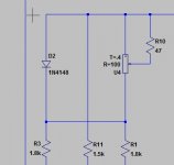
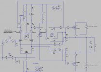
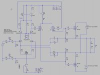
But you can build it as it is now so you can test on your speakers, on top of LTP R14 and R15 cut trace from supply and solder a 1n4148 and over this diode a ntc 200 ohms a serie resistor for tuning or maybe a pot over the diode and adjustment pin on one side of ntc and other on supply. you to do this on top of both resistors where she are connected, not on the mosfet side, see schematics.
regards
Attachments

That's a lot of changes - can you provide a diagram with notes drawn over actual photo of PCB so I know what to change? I can only build following a clear PCB layout diagram or silkscreen as I do not know the amp circuitry like you. No rush though as this amp is on back burner as I build my speaker project.
To get quite stable bias settings I have done the following, a darlington with collector to base npn transistor between R15 and R14 and supply, and two source resistors 0.22 ohm do let the amp prevent dias runout, however when let it be above 80 to 100 oC it go up again by 100 mA and stays there.
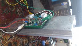
I have now put up the heatsink so air can flow better. now the amp heatsink is 65 oC and keeps stable on 500 mA plus minus 10 mA. This looks good.
Also I have read that a darlington is not needed, the temco of the servo can de adjusted with two resistors on base and one in the collector or emittor, to get tempco.
the Transistor do better then the NTC, however it do runtout when it get very hot, then it can go thermal runout, but for that happens we need more then 100 oC heat for heatsink, and maybe there are transistors who can get more regulation, a transistor with higher Hfe or just lower when overcompensate.
Now I have just a darlington as diode who sense temperature not as in schematic with resistors and a temco pot.
Later I go try as it is cold again because most of the time it is to high then, we need here some balance. so let you now later.
For the haters who do not like that LTP current is altered is this a way to prevent that because here we do only regulate gate voltages of VAS.
And as you see the PCB is quite damaged by all this experimenting, but we can never prevent this as it is a new design.
regards
Attachments
Last edited:
Hi X
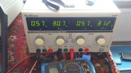
I have now the amp stable, when cold it idles on 501 mA and when hot, yes like 80 a 90 degree it idles on 530 mA.
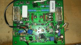
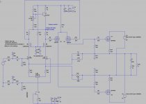
I have used a darlington in diode mode and put i two source resistors of 0.22 ohm 5 watts in the amp, (these has to by low inductance types). In schematic of prvious post I have put in a Vbe multiplier so I can adjust excactly, the ltp current is not altered and this do work nice incl with source resistors of 0.22 ohm.
Further the amp when put the VAS on earth level the amp is complete balanced, and no voltage anymore on output, like
Joe mentioned, but the HD is then only oneven harmonics, the even are complete canceled out, and as we all now the
sound can be less nice when we have only onevens, the long tail pair input is the cause, that is wahy some people do
not use them.
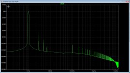
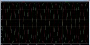
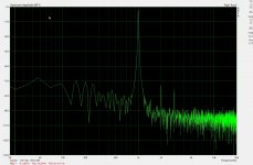
So need a way to get also this problem out of the world. see pictures of results.
regards
I have now the amp stable, when cold it idles on 501 mA and when hot, yes like 80 a 90 degree it idles on 530 mA.
I have used a darlington in diode mode and put i two source resistors of 0.22 ohm 5 watts in the amp, (these has to by low inductance types). In schematic of prvious post I have put in a Vbe multiplier so I can adjust excactly, the ltp current is not altered and this do work nice incl with source resistors of 0.22 ohm.
Further the amp when put the VAS on earth level the amp is complete balanced, and no voltage anymore on output, like
Joe mentioned, but the HD is then only oneven harmonics, the even are complete canceled out, and as we all now the
sound can be less nice when we have only onevens, the long tail pair input is the cause, that is wahy some people do
not use them.
So need a way to get also this problem out of the world. see pictures of results.
regards
Attachments
The idle problem is over, a vbe multiplier above the ltp input amp do the trick, the pot is for the temco, you need to adjust so that idle stays stable, even when heatsink is very hot, a little overcompensation is a wise idea so that when extreme hot idle go down.
after adjust you can replace the pot by two resistors.
Last pair photo,s are distortions in simulation, who never is accurate.
C3 and C4 is 100p forgotten to type it.
regards
after adjust you can replace the pot by two resistors.
Last pair photo,s are distortions in simulation, who never is accurate.
C3 and C4 is 100p forgotten to type it.
regards
Attachments

Hi Kees
IMHO .this type from input to output inherently fully balanced CFA amp will give the best sonic result driven with fully balanced input signal as is in your schematic , I think it will sound just OK , very dynamic , neutral and very very fast ,
what is also good is secondary option since it can be driven in SE mode to ,
and yes I like the way how you have solved DC bias stability problem .
Best Regards !
Attachments

I like the way how you have solved DC bias stability problem.
Agreed, this approach beats my earlier suggestion if there is no need to stabilize DC offset at the output. I had assumed you wanted to keep both output rails near 0 VDC over temperature, but of course, that is often not needed in practice.
With no need for 0 VDC at the outputs, you may want to consider designing out the B- supply. If you have (or can find) JFETs that will work well at Vgs of -2 to -3V (e.g. maybe selected J111-J112s), I think you could do this without having to bias up the JFETs and AC couple the inputs. You could then power the front end from a B+ made by summing and filtering the floating output stage power supplies, and do away with the separate front end B+ supply.
Hi Kees
IMHO .this type from input to output inherently fully balanced CFA amp will give the best sonic result driven with fully balanced input signal as is in your schematic , I think it will sound just OK , very dynamic , neutral and very very fast ,
what is also good is secondary option since it can be driven in SE mode to ,
and yes I like the way how you have solved DC bias stability problem .
Best Regards !
I have now adjust the temco, when cold it is 550 mA and when hot to bake a egg it jingle around 500/530 mA. it is time consuming to get good temco, so much variables, but when stay in 50 mA I think it is oke. I idle the fets 500 mA because she are not quite liniair as most verticals are, but irfp460 is better then the irfp240..
Now the heatsink is hot enough to bake a egg. and idle current settle on 550 mA.
Agreed, this approach beats my earlier suggestion if there is no need to stabilize DC offset at the output. I had assumed you wanted to keep both output rails near 0 VDC over temperature, but of course, that is often not needed in practice.
With no need for 0 VDC at the outputs, you may want to consider designing out the B- supply. If you have (or can find) JFETs that will work well at Vgs of -2 to -3V (e.g. maybe selected J111-J112s), I think you could do this without having to bias up the JFETs and AC couple the inputs. You could then power the front end from a B+ made by summing and filtering the floating output stage power supplies, and do away with the separate front end B+ supply.
Hi Joe
The offset on the output stays stable with temp because she cancel it out, for low distortion we need to measure the pair of jfets. I did test the resistors to earth and not to output rails, this give a output signal without the little offset whe acause is for both sides of circlotron equal so it has no offset, the version without the extra driver has 4 volts on output rails but also no offset. however the signal is lifted from the zero point and maybe the ltp get then unbalanced and so more distortion.
That is why I have ground the resistors, however the version with 150 ohms and differential driver do not work wel when I do change it, maybe because this amp has a driver who do work class a to drive the irfp240, or 460..
the newer version do well but it cancels out all the even harmonics to zero and let the uneven ones intact, so was my question what do the sound, the uneven ones are -80 or so.
The correction for idle do well, even when very hot it stays on nice 530 mA plus minus 20 mA on this moment, now it cools down again.
The front end is already changed, the voltage is on one side -10 volts 50 mA or so and +35 on top, this do work nice, I do not now what happens when change that to
one voltage, maybe making a negative supply with zener can work. this because of the temperature correction vbe on top of that ltp.
regards
Last edited:
The idle problem is over, a vbe multiplier above the ltp input amp do the trick, the pot is for the temco, you need to adjust so that idle stays stable, even when heatsink is very hot, a little overcompensation is a wise idea so that when extreme hot idle go down.
after adjust you can replace the pot by two resistors.
Last pair photo,s are distortions in simulation, who never is accurate.
C3 and C4 is 100p forgotten to type it.
regards
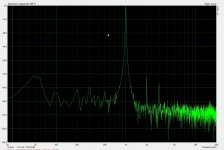
The last picture here where HD is 0.018 % is 100 Khz. the 0.001 is 1Khz, square is also 100Khz. this is the best way, with two extra fets in output as a source follower driver and a smaller frontend with smal mosfets driving the circlotron, this way it do have lowest distortion so we go make pcb for that.
The version with beefy driver in frontend can be used, it did sound quite oke, distortions are higher tough, also with measurement.
regards
The offset on the output stays stable with temp because she cancel it out
Understood. I was referring to absolute DC offset from each output to ground, not offset across the outputs. Sorry for any confusion there.
I have also used a zener to create B+/B- from a single supply. It works, but the B+ drops by the amount of the B-, so watch out for that, and also for supply noise, which you will still have on both supply rails. A single supply keeps all the noise on the B+, which can be helpful in cases where it's practical.
Hi Joe
The offset on the outputs are not a problem, however when measure it is out of what we normal see as normal, but because it is a cirlcotron it just do shift some voltage but on the end the offset on the speakers stays in the 10/100 mv earea, couple the jfets do even make it within 50 mv.
Your idea was to put the ccs jfet on ground? and then use a jfet with lower G on? like -2 -4 volts? also here we loose then some volts and I do not now what stability does.
What concerns the distance of supply noise this vas has not the best point to keep that out, I have however not noist problems, the oscilloscoop did has more, but for the frontend we need a stabilized supply, these days it very easy to make one, even with a minus 10 volt generator on board.
The distortion I have is because of the miller capacitance of the drivers who also amplify, the LTP has need a more beefy Jfet, like the PN4392 or 91 Jfet so we can set idle of ltp higher to get lower distortion, however, the new schematic with the extre source follower driver do a lot better, here the fets are very low capacitance to the ltp because she are in cascode, also putting resistors on ground removes the offset from output, but as mentioned this is not a problem except the modious effect.
regards
regards
Do we believe that when we go dead we get reborn?, well, this little girl has, because she sing this opera without ever be learn it, just from herselfs, this can be
prove that we take with us our experiences and knowledge, it just move with us..
https://www.youtube.com/watch?v=_NfnSgYqM4M
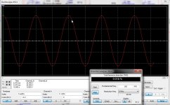
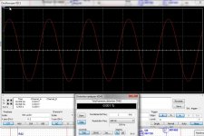
I have measure my amp, after it is done, the idle is stable and protected for open loper pot. But also have measure distortion of the hyrbid tube amp I use with 2sk1058 j162.
As you see distortion looks alike, I have also some offset on output of the pc audio card, I do use the AC97 on board, maybe a appart usb soundcard is better.
regards
prove that we take with us our experiences and knowledge, it just move with us..
https://www.youtube.com/watch?v=_NfnSgYqM4M
I have measure my amp, after it is done, the idle is stable and protected for open loper pot. But also have measure distortion of the hyrbid tube amp I use with 2sk1058 j162.
As you see distortion looks alike, I have also some offset on output of the pc audio card, I do use the AC97 on board, maybe a appart usb soundcard is better.
regards
Attachments
Kees
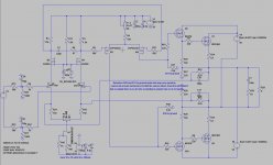
I think that Joe B. suggested something like this how to derive DC supply from OPS floating PSU`s for input/driver stage ,
it is done in the same way as is done by early Circlotron tube amps , but of course that zener diode can be replaced with some discrete stabilizator circuit .
regards
I think that Joe B. suggested something like this how to derive DC supply from OPS floating PSU`s for input/driver stage ,
it is done in the same way as is done by early Circlotron tube amps , but of course that zener diode can be replaced with some discrete stabilizator circuit .
regards
Attachments
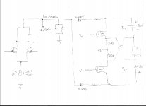
I think that Joe B. suggested something like this how to derive DC supply from OPS floating PSU`s for input/driver stage, it is done in the same way as is done by early Circlotron tube amps , but of course that zener diode can be replaced with some discrete stabilizator circuit.
Yes, but without the (1N4007) blocking diodes. The output stage supplies swing symmetrically and sum to a near-constant DC value over the full cycle. The filtering only has to absorb a small common-mode residual, which includes most of the supply ripple. Active regulation after that is ideal if you can afford the voltage loss. Otherwise, I'd suggest using a CRC filter.
Banat and Joe.
The idea is nice, using the circlotro voltages for the preamp, however the ccs to ground, I think I get trouble with the idle current who is also a part of the ltp section, it is just couple volts.
The 1n4007 diode is for protection when supply is wrong connected, is not needed, the combination of zeners and a resistor to remove supply resudals who is need when use the power supply, can replaced by a regulator (low drop?).
However the other design has a extra source follower so the driver section need 16 volts more to get full efficienty, for the low voltage section loss is gate on voltage x 1 and so halved\.
the driver section I go try to see what happens with a single supply 50 volts and a ccs with a jfet with -2 or -4 gate on voltage, then the drop will be enough but the current here is 10 a 15 ma plus the feedback current and go then maybe even to 20 ma, so need a jfet who can do this current and this one can do right.?.
http://www.mouser.com/ds/2/149/PN4391-889992.pdf
regards
The idea is nice, using the circlotro voltages for the preamp, however the ccs to ground, I think I get trouble with the idle current who is also a part of the ltp section, it is just couple volts.
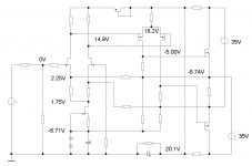
Kees, I had another look at your idea of using a zener (or equiv) to create a B- and now think it could work well. While there is a loss of B+, the loss is only relative to ground. If you reference the output rails to B-, the voltage across the VAS stays much the same, so you keep about the same output signal swing. Also, having a lower B+ may mean that you can avoid the need to cascode the input stage JFETs.
To illustrate, I modeled a 50W amplifier (35V supplies) and measured DC voltages at various points around the circuit. I used a rather small B- (about 6.7V), which worked fine in the model with J110 JFETs, but I think you could go to 10V with no problem. This would let you use 2SK170s for the input LTP and still have voltage left over for the CCS. Also, in the model I used a zener + diode for the B-, but in practice I'd probably try a shunt regulator IC.
Attachments
Hi Joe
The idea is nice however, the zeners wil get to much? I presume the resistors on VAS has choosen such that the current is not to high, because the driver VAS do idle on 30 mA each, making total of 60 mA.
The resistors before the VAS stage needs low ohmage otherwise there is a uge drop, what is caused because of the VAS current, I presume it is for decoupling.
regards
Joe and X and Banad.
I have started to do it over again, taking some things in account the version we have now has to much HD trouble, but it do sound nice, so ears have to decide.
I have a balanced version who has not the trouble of a LTP and a diff VAS, so it is interesting and a version who is the same as I got here but with changes such that capacitance on the LTP is removed, this is cause of a generation of uneven harmonics who is the only leftover, this TIM kind of distorting I do not like.
The balanced version have local feedbacks , so I a a kind of curious what this does.
X I have this amp working, as it is, for get a idea you need to build a channel to try.
for the balanced version I have a pcb design, for the irfp versions of mosfets.
Joe, have you some resistor values or the sim file for me?, les time consuming because I am not a mat boy.
regards
- Home
- Amplifiers
- Solid State
- allFET circlotron