I guess I will have to listen in mono for a while until I get another trafo. Pricey triple toroid amp. 🙂
Could each coil make two PSU's each with own rectifier? Wouldn't the rectifier be the interface of a new circuit? So 4 PSU's from one split cool trafo?
Could each coil make two PSU's each with own rectifier? Wouldn't the rectifier be the interface of a new circuit? So 4 PSU's from one split cool trafo?
I guess I will have to listen in mono for a while until I get another trafo. Pricey triple toroid amp. 🙂
Could each coil make two PSU's each with own rectifier? Wouldn't the rectifier be the interface of a new circuit? So 4 PSU's from one split cool trafo?
I think this will also short, throught the rectifier diode, maybe a scrapyard has a transformer? or secondhand somewhere.
I did buy them on a dump, but also has just one toroid. maybe making a SMPS ? with four output voltages, this is what I do some day, a resonant version.
regards
Those 53v Abletec SMPS for $25 may be the way to go. Only 1.5amps continuous though and 4.5amps peak.
Here a tread or treat? because of danger, making a circlotron supply.
http://www.diyaudio.com/forums/tubes-valves/178889-stereo-circlotron-using-only-two-supplies.html
We are not the only one with that experience, it is difficult to see what happens when use one supply, it can not be used.
regards
http://www.diyaudio.com/forums/tubes-valves/178889-stereo-circlotron-using-only-two-supplies.html
We are not the only one with that experience, it is difficult to see what happens when use one supply, it can not be used.
regards
Those 53v Abletec SMPS for $25 may be the way to go. Only 1.5amps continuous though and 4.5amps peak.
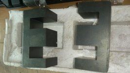
I have here a big core, can be used to 3500 watts, and is for a welder smps who I still have to make.
With this you can make a big supply, maybe even with all insolated voltages on one core, I have program to calculate that.
regards
Attachments
My own ignorance - but I will have to draw a simplified schematic of the output stage and the transformers and their PSU's hooked up to see the final current loops and where the shorts would occur if one were to use four independent rectified PSU's. It doesn't make sense that one has to have a transformer isolated PSU for this to work. The current schematic is drawn so small and with connectors jacks so it's not possible to analyze via looking at it. Must hand draw on sheet of paper now.
My own ignorance - but I will have to draw a simplified schematic of the output stage and the transformers and their PSU's hooked up to see the final current loops and where the shorts would occur if one were to use four independent rectified PSU's. It doesn't make sense that one has to have a transformer isolated PSU for this to work. The current schematic is drawn so small and with connectors jacks so it's not possible to analyze via looking at it. Must hand draw on sheet of paper now.
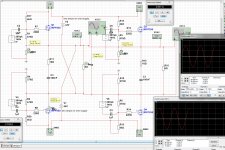
Here a schematic two on one, as I do see there are in sim no problems, so difficult to see, maybe when one amp draws more amps because of music offset can flucuate on the other?.
regards
Attachments
Last edited:
Have you already did find it X, I have, it is not possible with one supply, speakers are connected to each other just get another balanced amp with 2 x power or such and not a shorth between speakers.
regards
regards
Attachments

Last edited:
So not sure what you are saying. So we have to use two independent power supplies per speaker? And by independent - meaning cannot have common ground even? It may be possible to wire it in a cross? For example with a toroidal trafo with dual 35v secondaries can make two isolated sets of PSU's. Each of those PSU's (called A1 and A2) will have a common ground but not with respect to the second output winding which will have PSU's (B1 and B2). Now, for amp 1 we use PSU A1 and B1 and they don't share same common. On second amp use A2 and B2. Will that work?
But that's just academic as my situation is I would have to buy another matching trafo to my 32v 300va (44v rails) and make four PSU's.
But that's just academic as my situation is I would have to buy another matching trafo to my 32v 300va (44v rails) and make four PSU's.
Last edited:
If you look at the connections from the speakers, it result in that both amps on one supply feed the two speakers in paralel form, she are connected to each other.
you need two power transformers, one for each channel and one transformer for a stereo preamp driver section, the earth reference go throuth reference resistors as you now.R28 and R29 to preamp. circlotron is a floating amp but voltage to earth is not more then 2,6 volts I did sim, offset pot is very sensitive, so we look whatt happens, maybe we need a servo, but later care. you can not use one transformer and make two rectifiers with onwn caps for double it for stereo, it will still give trouble, even more.
Just look at a scrapyard or second hand store if there is a transformer, one with 4 windows 35 v 10 amp are also a possibillity or buy a empy toroid with only primaire windings and wind youself, it possible with some handy vingers.
Hi
Your project interested me more.
Do you planned a protection system ?
Output power supply could be reduced to use 400VA 2*25V transformer ?
I already have two
thanks
Your project interested me more.
Do you planned a protection system ?
Output power supply could be reduced to use 400VA 2*25V transformer ?
I already have two
thanks
Hi
Your project interested me more.
Do you planned a protection system ?
Output power supply could be reduced to use 400VA 2*25V transformer ?
I already have two
thanks
Hi
Yes you can use 2 x 25 volts ac as input for supply,circlotron, you get just less output voltage before clipping. 35 volts is fine, I do use 55 volts because I have that transformer. and class ab.
A protection system for the speakers I did not yet make, but there are plenty examples on the net or ebay.
Speaker BTL Protection Board | eBay
regards
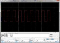
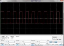
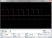
I did sim with lower voltages also for the drivers, because of current sources it is quite easy to change that.
However output power is lower afcouse, but better for class A low power amp.
pictures square = 20 Khz, 50 Khz and 100 Khz.
Resistor changes are R12, R13 = 680 ohm, R10 = 1k, R11 = 820 ohm, R4 = 680ohm, wattages the same, this was needed to get proper zener regulation,
regards
However output power is lower afcouse, but better for class A low power amp.
pictures square = 20 Khz, 50 Khz and 100 Khz.
Resistor changes are R12, R13 = 680 ohm, R10 = 1k, R11 = 820 ohm, R4 = 680ohm, wattages the same, this was needed to get proper zener regulation,
regards
Attachments
Last edited:
I need high quality 22pF and 680 pF capacitors, but see not much audio grade ones, ceramic caps here is no no, special the feedback capacitors who are there to remove overshoots.
Maybe somewone have a idea, like wima caps or styroflex.
regards
Maybe somewone have a idea, like wima caps or styroflex.
regards
Thanks to your answer
could you share spice model you used ?
An idea for caps : Silver Mica
http://www.mouser.fr/ProductDetail/...=sGAEpiMZZMtLiKaZgV7flaaRNIxO5MlAKbAZjZL3F3U=
could you share spice model you used ?
An idea for caps : Silver Mica
http://www.mouser.fr/ProductDetail/...=sGAEpiMZZMtLiKaZgV7flaaRNIxO5MlAKbAZjZL3F3U=
Last edited:
Thanks to your answer
could you share spice model you used ?
An idea for caps : Silver Mica
http://www.mouser.fr/ProductDetail/...=sGAEpiMZZMtLiKaZgV7flaaRNIxO5MlAKbAZjZL3F3U=
What spice you need? I have done it in multisim and LTspice, for the last then you need maybe some models you can miss.
I have found the caps on ebay, cheaper then mouser because you need there order a mimimun to avoid extra costs.
regards
I need high quality 22pF and 680 pF capacitors, but see not much audio grade ones, ceramic caps here is no no, special the feedback capacitors who are there to remove overshoots.
Maybe somewone have a idea, like wima caps or styroflex.
regards
I just bought a bag of 680pF 5% MKT film caps. Probably perfect for this.
https://m.de.aliexpress.com/item/32723863975.html
22pF value is too small for film so probably NP0 ceramic should be fine.
Last edited:
I just bought a bag of 680pF 5% MKT film caps. Probably perfect for this.
https://m.de.aliexpress.com/item/32723863975.html
Are oke, the 750 pf can be just 680, low pass will be some higher with no consequenses, (hmm do I write it oke).
you need also 22pF these need high quality low leak, it is a feedback loop.
regards
Attachments

Last edited:
LTspice If possible
Mouser is just for exemple
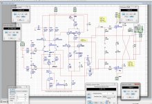
Here is a ltspice schematic of the circlotron. I have change it for low voltage, 35 volts driver 25 volts circlotron. If you see faults let us now, you can use also 25 volts for driver as I did mention earlyer.
regards
Attachments
- Home
- Amplifiers
- Solid State
- allFET circlotron