Can you name a Hitachi amp that used the all-FET circuit? I was going to correct Wahab (I would've been incorrect and edited the post) and say that the HMA-9500 MK1 used it, but I am 90% sure it didn't (the MK2 has a FET for the LTP, but the rest of the VAS is BJT-based, as are all other amps that came after the 7500).
I have a very rough copy of the 9500 MK1 schem somewhere. I am 90% it's not all-FET. I even have a 9500 in my collection, but I don't have time to squint at all the transistors and work out if they are FETs or BJTs at this moment (I was planning to put a Cordell DH-200 conversion into the enclosure, as I suspect it'll blow the 9500 away). I think that had Hitachi ever made an all-FET VAS / Lateral FET amp, it would've been the 9500 Mk1 as it was the bigger sister to the 7500 and one of their very first Lat-FET amps.
If anyone can make a successful amp out of the all-FET topology in the PDF, then I take my hat off to them. I am not aware of it being used commercially. Having seen that the 7500 has slightly less noise than its successors (Hitachi own specs), and having tested one on my UPV (-106dBV @ 10W into 4R7), I very much doubt it will outperform the All-BJT amp that the 7500 (and Maplin in the UK) used. I think Wahab pretty much suggested this would be the case earlier in the thread. I made a video of the 7500 connected to the UPV, as I was freaked out that a 1978 amp could deliver performance that's better than most amps coming out today (class A/B amps that is, not the class D types that have 0.00000 performance).
Thanks, Wahab.
I am reminded of what put me off restoring my 9500 and putting the Cordell circuit into the enclosure: the ominous looking 'protector' black box... What's in that? I very much doubt that the 9500 (either version) has lower noise or distortion than the 7500. I can't see the LTP FETs in the 9500 having lower noise than the 2SA872 used in 7500.
I am reminded of what put me off restoring my 9500 and putting the Cordell circuit into the enclosure: the ominous looking 'protector' black box... What's in that? I very much doubt that the 9500 (either version) has lower noise or distortion than the 7500. I can't see the LTP FETs in the 9500 having lower noise than the 2SA872 used in 7500.
Hi Wahab:
I increased C3 and C2 to 330pf and 68pf respectively. I re-connected the 220pf. And the magic is that the oscillations vanished and the zobel resistor is just cold.
I had to re-adjust the quiescent current.
I played some music for 10 minutes. Everything seems perfect. I am not using the resonance circuit.
But will the modification increase the distortion?
Should I settle with this?
Also generally recommended quiescent current for 2sk1058 is 100ma as I have seen in various designs. Is 50ma enough?
Hi Wahab:
I increased C3 and C2 to 330pf and 68pf respectively. I re-connected the 220pf. And the magic is that the oscillations vanished and the zobel resistor is just cold.
I had to re-adjust the quiescent current.
I played some music for 10 minutes. Everything seems perfect. I am not using the resonance circuit.
But will the modification increase the distortion?
Should I settle with this?
Glad that this was solved, the distorsion will not be affected because the TMC contribution is also boosted with the increased
compensation as long as the 10k resistance has not been modded, so the distorsion correction will be the same.
In principle you dont need more than those 50mA/device as there s 3 pairs that are parraleled and 100mA was
necessary for amps using only a pair of devices.
Now that it is stable you can increase the gain according to your liking and this should increase stability further to what
has been done, guess that your 50mA/device former quiescent current included the comsumption due to the oscillations
being dumped in the Zobel resistance, hence the need to readjust it once the oscillations are tamed.
As explained above all you have to do to increase the gain is to set the 1.5k R13 resistance according to your needs,
the gain is set by the ratio R14/R13, so if you want 1.5x more gain at 47x use a 1k for R13, and if you want to reach full power
with your smartphone eventualy that a 820R with a corresponding gain of 56x would be required.
Anyway sorry for all the troubles you experienced, hope you ll rightfully and deservedly enjoy your amp,
that s one of the first of its kind and should be better than Hitachi s own commercial amps when it comes to linearity
as they didnt implement cascoded VASs and that makes all the difference, the simulator may not be always 100%
accurate but the difference between simple and cascoded VAS is way too big to just be a simulation artifact.
Last edited:

Yes Patrick, Hitachi published that all FET design, but when you look at their power amps of the time with Lateral outputs (7500, 8500 and 9500 in orig and MK11 forms) they were all BJT/FET designs.
There maybe a reason why Hitachi never did a commercial product with an all Fet design.
@wahab, based on the member Iganymis and his testing, is this design stable or does it need more work - just asking having read the last 2 pages of posts here this morning.
There maybe a reason why Hitachi never did a commercial product with an all Fet design.
@wahab, based on the member Iganymis and his testing, is this design stable or does it need more work - just asking having read the last 2 pages of posts here this morning.
Last edited:
@wahab
Thanks Wahab. You and your team on DIY audio have designed a wonderful audio amplifier. Myself and anyone following this thread should thank you for a lot of theoretical and practical solutions that you have provided that would improve our electronics knowledge.
I have tried all combinations now and the three changes - C3 and C2 to 330pf and 68pf respectively, 220pf parallel to R4 and C11 to 1nf should solve the oscillation issue.
I played the amplifier for more than hour at listening volume for a room and all components are behaving perfectly.
Audio quality is just top-notch. Especially the fidelity at higher frequencies. Vocals also fill the room like in Class-A amplifiers.
If you wish, you can make these changes to the circuit when you find time and post it. I assure that it works flawlessly first attempt.
If I find time tomorrow, I shall try to test run it again and update you.
Sometime next week I shall try to shift boards to a cabinet and update you.
Ganesh Laxmanmurthy
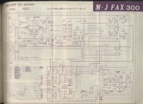
Just for reference - 9500mk2:
https://hubdynamolight.blog.ss-blog.jp/upload/detail/m_HMA9500mk2.jpg.html
https://hubdynamolight.blog.ss-blog.jp/upload/detail/m_HMA9500mk2.jpg.html
@gaborbela
Hi Gabor:
Your conversation on this thread motivated me to build this amplifier. Actually I got the PCBs done 4 years back. Finally completed it now. I wish you also complete the amplifier.
Ganesh
Hi Gabor:
Your conversation on this thread motivated me to build this amplifier. Actually I got the PCBs done 4 years back. Finally completed it now. I wish you also complete the amplifier.
Ganesh
Exactly, a fet input, then all BJT then lateral fet outs. The 7500 and 8500 did not even have the input fet - all BJT/Fet outputs.Just for reference - 9500mk2:
Correction, the 8500 Mk11 had the fet input like the 9500 Mk11 - then as I said BJT / lateral fet outputs.
@lganimys, thank you for your kind words, that s an immense satisfaction that you got the amp working flawlessly,
and hope that you ll enojy fully the fruits of your efforts, that was quite a journey, and in the pressure i even made a confusion
since the C11 cap value is of no importance as i had in mind another version of this amp that use a bipolar OS
and whose VAS emitters have a cap connected to the +V, the only difference with a 1nF will be that at power on the amp
will settle faster by a few us.
You did well to reconnect the C14 220pF cap // with R4 as without it the bandwith is too much extended, as it is now
with this 220pF and 68pF + 330pF updates it still has a 800kHz bandwith, so the compensation and frequency limitation
were the two issues as previously the bandwith was 1.1MHz.
If you increase the gain the bandwith will be reduced by as much as the gain increasement, if you settle for
a 48x gain FI, wich is 1.5x more gain, the bandwith will be 800/1.5 = 533kHz.
A by product of the gain increasement is that stabililty will also increase in proportion.
Lastly i would suggest to remove the C6 220pF cap as it extend the amp bandwith when the amp is uncompensated,
once compensated it has not much influence but one never knows, it is a remnant of a version using a bipolar power stage.
Thanks to you tests il post the updated schematic in a few times, actualy you were the cornerstone that made this design
an enjoyable amp for any interested user here.
As you could suspect i cant guarantee anything, lganyms got it working and as such he s the only reference since
another user didnt gave any news here other than he built it and got it finaly working but with a single latfets pair,
possibly that with a single pair the amp is slowed enough as to not needing a more robust compensation.
What i can say is that a 1MHz BW was eventualy too much given the 120dB OLG with the fact that cascodes
increase both the BW and gain we start with when uncompensated, and in this respect i would recommend also
to remove the C6 220pF cap as last mod, if it end being necessary it can always be added without modding
a PCB but so far it seems useless with a latfet output stage.
and hope that you ll enojy fully the fruits of your efforts, that was quite a journey, and in the pressure i even made a confusion
since the C11 cap value is of no importance as i had in mind another version of this amp that use a bipolar OS
and whose VAS emitters have a cap connected to the +V, the only difference with a 1nF will be that at power on the amp
will settle faster by a few us.
You did well to reconnect the C14 220pF cap // with R4 as without it the bandwith is too much extended, as it is now
with this 220pF and 68pF + 330pF updates it still has a 800kHz bandwith, so the compensation and frequency limitation
were the two issues as previously the bandwith was 1.1MHz.
If you increase the gain the bandwith will be reduced by as much as the gain increasement, if you settle for
a 48x gain FI, wich is 1.5x more gain, the bandwith will be 800/1.5 = 533kHz.
A by product of the gain increasement is that stabililty will also increase in proportion.
Lastly i would suggest to remove the C6 220pF cap as it extend the amp bandwith when the amp is uncompensated,
once compensated it has not much influence but one never knows, it is a remnant of a version using a bipolar power stage.
Thanks to you tests il post the updated schematic in a few times, actualy you were the cornerstone that made this design
an enjoyable amp for any interested user here.
@wahab, based on the member Iganymis and his testing, is this design stable or does it need more work - just asking having read the last 2 pages of posts here this morning.
As you could suspect i cant guarantee anything, lganyms got it working and as such he s the only reference since
another user didnt gave any news here other than he built it and got it finaly working but with a single latfets pair,
possibly that with a single pair the amp is slowed enough as to not needing a more robust compensation.
What i can say is that a 1MHz BW was eventualy too much given the 120dB OLG with the fact that cascodes
increase both the BW and gain we start with when uncompensated, and in this respect i would recommend also
to remove the C6 220pF cap as last mod, if it end being necessary it can always be added without modding
a PCB but so far it seems useless with a latfet output stage.
Thanks for the reply wahab, I look forward to you posting a new revised schematic once Iganimys is happy with his build.
@Iganimys where did you get your pcb's done and what gerber files did you use - thanks?
@Iganimys where did you get your pcb's done and what gerber files did you use - thanks?
There maybe a reason why Hitachi never did a commercial product with an all Fet design.
Very simple reason, because it is too expensive to use matched devices in a commercial product.
Those words came from someone who designed for Levinson.
The brands who still use FETs all round in products have them manufactured in low-cost countries.
Only exception is maybe Nelson.
But his have a different price tag.
Patrick
Back in the 1980's when Hitachi did this work, I do not think the cost of matching fets at that time would have been the issue - after all they had access to countless thousands of the fets at factory pricing and the wage costs back then were a lot lower. I am talking only about Hitachi - not other amp manufacturers who would not have lower cost access to these fets. Then, even back then these amps sold for quite an amount compared to more conventional amps.
So, really the question remains - why did Hitachi not produce a commercial product - after all they put in all the work to publish schematics in their documents. There are other reasons in play here I feel.
Patrick, I wish you well in your all Fet design/testing, but there might be hurdles due to the fact that many of the small signal fets in the published design are not available and subs will need to be considered carefully ( and those words come from another esteemed member around here), But I will be the 1st to congratulate you when you have a stable and working tested design up and running.
If you are thinking about a future GB for this amp, you will have to offer the pcb and the fets for willing members to complete a working amp, members who start making subs with active components will be asking for trouble.
Last edited:
This is silly. Matching Fets is not expensive. It does presume you have adequate inventory.
On another note, I imagine that Hitachi was interested in selling transistors, not finished amplifiers.
😎
On another note, I imagine that Hitachi was interested in selling transistors, not finished amplifiers.
😎
This is silly. Matching Fets is not expensive. It does presume you have adequate inventory.
Nelson,
You know him who used to design for Levinson.
Those were his words in a private communication.
So no FETs (allowed) in products he designed.
Patrick
This is silly. Matching Fets is not expensive. It does presume you have adequate inventory.
Nelson,
You know him who used to design for Levinson.
Those were his words in a private communication.
So no FETs (allowed) in products he designed.
Patrick
- Home
- Amplifiers
- Solid State
- All Hitachi Lateral FET amplifier for DIY described by Paul Kemble