That s just asc files, on the other hand at least i posted numbers.
Btw, neither of the two Hitachi amps in the AN are definitive designs, they got the THD numbers thanks to vastly
undersized compensations that render the amps very conditionaly stable, guess that you didnt spot the two zobel
cells at the output of the full fet version, so Allister numbers, wich are all extracted from Hitachi s AN, are worthless
if not fraudulous since he did no measurements and is just quoting Hitachi s graph s numbers.
Also you didnt notice that they have only 20dB gain while i used 30dB all while having much less THD + IMD, robust
stability without any output inductance and roughy 100x the PSRR, all "details" that do not count for you, but true
that the goal is not the same as i shoot for free high perfs while your aim is just useless differention to have a selling point
for some PCB and/or eventualy components.
I ll add that the design i proposed is not voltage dependant and can be used with 2 x 15V to 2 x 50V AC transformers
with only the quiescent current to adust, wich is not the case of the raw AN designs.
Last edited:
PDF attached (condensed version)
Aside from the 7500 MK1, the 7500 MK2, 8500 MK2, 9500 MK1/2 have hybrid FET inputs with BJTS for the VAS. I have a 9500 MK1 and wondered if it were based on the all-FET apps book, but I have edited the post to correct myself. I don't have a schematic for for it, but I suspect 9500 MK1 is hybrid, not all-FET.
Aside from the 7500 MK1, the 7500 MK2, 8500 MK2, 9500 MK1/2 have hybrid FET inputs with BJTS for the VAS. I have a 9500 MK1 and wondered if it were based on the all-FET apps book, but I have edited the post to correct myself. I don't have a schematic for for it, but I suspect 9500 MK1 is hybrid, not all-FET.
Attachments
Last edited:
Many thanks for the Hitachi data book, will make interesting reading.
I think the Hitachi amps were based on the BJT/FET circuits. Not sure if there was ever an all FET amp commercially made by Hitachi back then- but stand to be corrected on that.
The 9500 hit an input fet and all other actives were BJT with fet outputs. The 7500 did not have the fet input transistor.
Last edited:
Hi Wahab:
@wahab
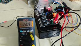
I tested the amplifier in real time before assembling it to an enclosure.
50ma per Mosfet quiescent current is set.
Now the sound quality is just top-notch.
But I ran into a small problem.
The resistor in the Zobel network (R-31 - 10E 3W) is heating up(very hot) in a minute into sound volume set to low listening room level. Same issue with both the channels.
All the other components are properly behaving.
Could it be because I am using a 4 ohms speaker to test? Or do we need a resonance circuit (10E with a coil wound on it) ?
If this is resolved, I can shift it to the enclosure.
Kindly suggest.
Ganesh
@wahab
I tested the amplifier in real time before assembling it to an enclosure.
50ma per Mosfet quiescent current is set.
Now the sound quality is just top-notch.
But I ran into a small problem.
The resistor in the Zobel network (R-31 - 10E 3W) is heating up(very hot) in a minute into sound volume set to low listening room level. Same issue with both the channels.
All the other components are properly behaving.
Could it be because I am using a 4 ohms speaker to test? Or do we need a resonance circuit (10E with a coil wound on it) ?
If this is resolved, I can shift it to the enclosure.
Kindly suggest.
Ganesh
Attachments
That s not the load, that s an oscillation that is occuring, as you suggest try to put a small inductance parraleled with a 1-2R resistance in serial with the speaker, if the issue persist that may be due to the ground connection between signal ground and HC (high current ground) with the 1R, but let s see one thing after the other, and since i proposed the design i ll provide all necessary
support to sort out this issue.
support to sort out this issue.
Last edited:
There s another possibilty to test but it must be done separately from the coil test and is the 220pf cap that was
lately soldered with R4, it improve the behaviour at normal loads by slowing down a half of theVAS, although
this add a tiny amount of THD, but with a 1uF capacitive load it slow down too much this side of the VAS,
try removing it while having no coil at all.
Anyway be sure that this will be solved one way or another, the coil + R will likely clear the issue but it would be better
to have total stability without it even in presence of capacitive loads.
Next is to remove the 220pF that was parraleled with R4 and do a test without output coil.
If it doesnt then the oscillation may be created by a gound loop, namely R34, try removing it if removing the 220pF cap
doesnt solve the issue, i didnt look at the PCB but the ground of the output zobel network must get separately
to the PSU ground star point in all cases, i think that it s respected in the board.
I think the Hitachi amps were based on the BJT/FET circuits. Not sure if there was ever an all FET amp commercially made by Hitachi back then- but stand to be corrected on that.
Last page of the pdf above, post #482 :
Patrick
Last edited:
Reduce the C11 cap that is 100nF down to 1nF, and dont be worried, we still have a lot of bullets.
All those caps, the 220pF and 100nF were here to slow down the amp, so the changes wont affect the perfs,
actually they will increase a little but this will allow us to mod the compensation in last ressort and still
get back on our feets perfs wise.
All those caps, the 220pF and 100nF were here to slow down the amp, so the changes wont affect the perfs,
actually they will increase a little but this will allow us to mod the compensation in last ressort and still
get back on our feets perfs wise.
I shall do it now. I need to remove the board from the heatsink to modify.
Also the input sensitivity is a bit low.
Also the input sensitivity is a bit low.
The input sensitivity is set for CD player levels with a gain of about 32dB, you can increase it without changing anything
else by setting R13, wich is 1.5k, to the desired value, at 1k this will increase the gain by 1.5x wich will be 48x or 33.6dB.
Smartphones with analog jacks ouput about 700mV pk at full volume, this would require a 56x gain and setting R13 at 820R
if you want to directly drive the amp with such a source.
Output noise will of course increase accordingly but it s low to start with, another consequence is that stability
is inherently improved, so if you do the gain change at the same time as for the cap we may not know who is the real culprit,
it would be better to stabilise the amp first and then increase gain on top knowing that it will improve things further anyway.
Last edited:
One other thing that I observed is that initially when I increase the volume, the current draw increases rapidly and then starts to rapidly decrease.
There is some problem somewhere. I rechecked the components and all are as per the circuit.
There is some problem somewhere. I rechecked the components and all are as per the circuit.
Next is to increase the compensation by about 1.5x, set C3/C2 from 220pF/47pF to 330pF/68pF,
if you dont have a 68pF at hand use a 82pF or 100pF for the time if you have one at disposal,
same with the 330pF, just connect the removed 220pF in parralel with the compensation existing 220pF.
The current variation may be related to the oscillation, it could be that at a higher volume the oscillation
is reduced or suppressed once the current in the laterals has reached a given threshold.
Edit : Dont forget to short the input to ground for all tests.
Last edited:
- Home
- Amplifiers
- Solid State
- All Hitachi Lateral FET amplifier for DIY described by Paul Kemble