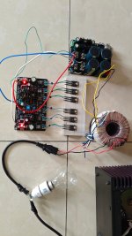
Switched it on for testing with transistors mounted on a test heatsink plate. After about 1 minute, no smoke or no component is getting heated up. Shall go ahead taking some voltage measurements. If things seem alright, I shall measure the voltage at the speaker terminals and connect speaker to test.
Attachments

Wahab, I added a 220pf capacitor in parallel with R4.That should be good as long as it allow to set the curent easily, anyway the two diodes in parralel will limit any wrong doing,
also you could add the 330pf capacitor i mentioned in parralel with R4, 220pF is enough actualy, eventualy the amp
can work without it but it s more cautious to add it as this render the circuit less dependant of the transistors parameters
when it comes to stability.
If you test with +-55V on the first try then put 3-5W 20-50R resistances in serial with the +- supply lines,
or a 40-50W incandescent light bulb in serial with the transformer primary.
Great, there s a member who got some issues because he used other transistors and he got it working by implementing
the correct ones, i suspect that it was due to the lack of this capacitor as normaly it should be quite immune to the transistors
used, there s other models that can be used in some places.
Also in principle the mosfets gates resistances, R19-21 and R28-30, should be as close as possible from the transistors pins,
and btw, wich laterals brand and models did you use.?.
Thanks. Laterals are from Renesas. Jfets are matched LSK170. I have used A992, A1360 and C3423. BC546/BC556 are KEC. All small value caps are WIMA. Resistors of MFRs but ordinary quality.
This setup is just for testing. I shall mount the board and the obviously the Mosfets on a large heatsink. (You can visit my site theheatsink.com where I sell heat sinks)
Tomorrow I shall do the sound test and let you know the results. In couple of weeks, I shall do the actual build (Fully discrete setup)
Hi Wahab, Gabor, Alex and everyone who has contributed for this project:
I tested this amplifier for working. (Very crudely at this point).
It works out of the box. All components are behaving as supposed to be. Nothing is overheating.
Voltage at the speaker terminals is near zero.
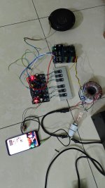
Now I just connected a crude ordinary 4ohms car speaker to test. I played some music from Youtube and a few DSD songs from media player.
No tone-control or equalizer was connected in-between.
1. The amplifier is dead silent.
2. I can just say that the sonic quality is out of this world. Sound is crisp. Fidelity is top-notch. Lows and Highs are exactly as supposed to be. A very different lively feeling compared to any other amplifier.
I am saying this as I have built many Mosfet and BJT amplifiers. (Except Sony Vfet). I have listened to many high-end branded amplifiers including a model of McIntosh.
My recent builds are Modified Apex A-40 and peeceebee v4h.
So hats off to Wahab, Gabor, Alex and all the others who have contributed for this design.
I shall update once I properly mount the boards on to a suitable cabinet. I shall try to do it in next couple of weeks.
Ganesh
I tested this amplifier for working. (Very crudely at this point).
It works out of the box. All components are behaving as supposed to be. Nothing is overheating.
Voltage at the speaker terminals is near zero.
Now I just connected a crude ordinary 4ohms car speaker to test. I played some music from Youtube and a few DSD songs from media player.
No tone-control or equalizer was connected in-between.
1. The amplifier is dead silent.
2. I can just say that the sonic quality is out of this world. Sound is crisp. Fidelity is top-notch. Lows and Highs are exactly as supposed to be. A very different lively feeling compared to any other amplifier.
I am saying this as I have built many Mosfet and BJT amplifiers. (Except Sony Vfet). I have listened to many high-end branded amplifiers including a model of McIntosh.
My recent builds are Modified Apex A-40 and peeceebee v4h.
So hats off to Wahab, Gabor, Alex and all the others who have contributed for this design.
I shall update once I properly mount the boards on to a suitable cabinet. I shall try to do it in next couple of weeks.
Ganesh
Attachments
Last edited:
Thanks Gabor. Once I complete the project, I shall make a video and post. By the way, how is your health now?
Unfortunately the same, not much change. Thanks for your question, Appreciated!
Your build will motivate to power up my PCB-s also.
My PCB was designed by me, I did not used the Alex design (bad decision) and now I have second thoughts if will work or not.
Video or sound test will be great!
Greetings
Your build will motivate to power up my PCB-s also.
My PCB was designed by me, I did not used the Alex design (bad decision) and now I have second thoughts if will work or not.
Video or sound test will be great!
Greetings
@lganimys , glad that everything work flawlessly, high voltages like +-55V always makes me anxious even with proved designs,
let us know how things fare once the amp is definitly cased.
@gaborbela , Alex s PCB is indeed awsome but aesthetics is not the whole story, your PCB is very cool and way enough,
what matters is the ground routings, for the rest your large tracks are a plus, just do conform grounds connections with
the PSU and you ll get exactly the same perfs.
We all agree, a great circuit - it's a real pleasure to marvel at the schematic alone ... 🙂
#
Please be careful with the handling of your rails, +/- 55Vdc is not without danger.
I've already encountered higher voltages of up to 350Vdc twice in my life and have been very lucky each time. The first time, the circuit board flew through the entire laboratory as a reaction of my muscles, the second time (almost 30 years later) I had no good feelings in my entire forearm for weeks ..!
Hi Wahab,
I have a question.
I am building the power supply for the amplifier. It is a regular bridge rectifier based dual power supply.
For the bridge, are normal bridges like KBPC5010 better or shall I build the bridge using ultra-fast, soft recovery diodes such as RHR30120 or MUR860 etc. ?
The motive is to reduce or eliminate the switching noise and current leak at the time of switching. Regular diodes suffer from these. But ultrafast diodes are schottky diodes meant for different application.
I looked into many debates regarding this and still unable to decide.
I have required number of RHR30120 with me that I can use.
Kindly suggest.
Ganesh Laxmanmurthy
www.diyaudio.com/community/threads/i-heard-about-the-linear-audio-article-on-soft-recovery-diodes-and.285093/
Linear Audio is no longer available, but you can ask the author of the article.
Patrick
Linear Audio is no longer available, but you can ask the author of the article.
Patrick
This problem can eventually arise in very poorly designed amps that have so low PSRR that any PSU noise will findHi Wahab,
I have a question.
I am building the power supply for the amplifier. It is a regular bridge rectifier based dual power supply.
For the bridge, are normal bridges like KBPC5010 better or shall I build the bridge using ultra-fast, soft recovery diodes such as RHR30120 or MUR860 etc. ?
The motive is to reduce or eliminate the switching noise and current leak at the time of switching. Regular diodes suffer from these. But ultrafast diodes are schottky diodes meant for different application.
I looked into many debates regarding this and still unable to decide.
I have required number of RHR30120 with me that I can use.
Kindly suggest.
Ganesh Laxmanmurthy
its way to the amp output, you ll find those half baked designs in DIY forums with the low NFB and class A ones getting the prize.
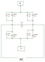
There s no need of fast recovery diodes, use a beefy bridge and add a few low value caps
in a configuration that made its proofs.
I post a schematic, the 47nF cap is just here for the noise from the main, JVC use as much as 0.1 to 0.22nF FI,
the 10nF ones adress any switching noise in case the big filtering caps have too high impedance at high frequencies.
Attachments
You re welcome, you can eventualy also add some 0.22 to 0.47uF MKP cap in parralel with the filtering cap,
this could also help with the main and diodes noise, so far the main noise is the only problem i have encountered
with some amps, FI when a refrigerator is turned on, nowadays some SMPS can also add a pollution of the main,
a 0.22uF MKP at the transfo input can help in this case, moreover with some basic inductance in serial.
@wahab
Hi Wahab:
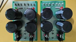
Power supplies for the two channels are almost ready. As you can see, they are built on general purpose PCBs.
It is rather a simple regular dual power supply but with enough filter capacitance. (15000uf x 4 per channel tested for the value and ESR)
I have added 10nf capacitors in parallel to diodes on the bridge and 0.1uf capacitors as per your suggestion.
The diodes in the bridge are RHR30120 which are ultrafast and soft-recovery types. They are capable of 30 amps of current as per the datasheet. These diodes boast 50% less recovery time and very low switching noise.
All the inter-connections among the components are done using 16AWG copper wire capable of carrying 18 amps of current.
Kindly suggest if any thing else is required.
Ganesh Laxmanmurthy
Hi Wahab:
Power supplies for the two channels are almost ready. As you can see, they are built on general purpose PCBs.
It is rather a simple regular dual power supply but with enough filter capacitance. (15000uf x 4 per channel tested for the value and ESR)
I have added 10nf capacitors in parallel to diodes on the bridge and 0.1uf capacitors as per your suggestion.
The diodes in the bridge are RHR30120 which are ultrafast and soft-recovery types. They are capable of 30 amps of current as per the datasheet. These diodes boast 50% less recovery time and very low switching noise.
All the inter-connections among the components are done using 16AWG copper wire capable of carrying 18 amps of current.
Kindly suggest if any thing else is required.
Ganesh Laxmanmurthy
Attachments
Hi @lganimys, that s very nicely done, there s apparently nothing left other than enclosing this nice build in a case,
the amp has very good PSRR and your huge caps will definitly crush any residual noise that may appear all while providing
exceptional dynamics for transients.
Just dont forget to add a speakers protection, we are never cautious enough in this register as often speakers cost more than amps, and of course tell us about your listening tests with your definitve speakers, this will be much appreciated as there s very few lateral fets build by here, moreover with 100W power capability.
- Home
- Amplifiers
- Solid State
- All Hitachi Lateral FET amplifier for DIY described by Paul Kemble