Where to get 2SK117 ?
BL grade is next to impossible to get.
GR grade is easier, which is sufficient for the task above.
Here is one which says specifically Toshiba :
https://www.reichelt.de/jfet-n-ch-50v-5ma-0-3w-to-92-2sk-117-p2143.html
Reichelt is as big a component supplier as any other.
So no motivation for them to cheat.
And they will refund if article is not genuine.
I use them a lot, but have not bought 2SK117 from them.
Pretty sure there are other sources.
2SK209 is identical to 2SK117 but in SOT23.
I would not use them for more than 50mW dissipation.
Other alternatives are 2SK223 or 2SK373.
Probably even more difficult to find.
Patrick
Last edited:
Sometimes i wish it was possible to like the same post multiple times 👍🍻I just bumped into this, and I am not about to build a Class AB Hitachi design.
But I found it quite interesting how much the circuit has been changed since post #1 in 2012.
Especially when the title said “All Hitachi MOSFET amp”. 😊
Of course the comments at the Paul Kemble webpage is rather tempting :
https://www.angelfire.com/sd/paulkemble/sound7g.html
"For whatever reason, the thing worked very well. I was doing an MSc in the Audio engineering lab under Malcolm Hawksford at Essex University at the time. We knocked some up and were quite taken aback by how good they were …. and there were innumerable commercial clones. It's one of those very simple circuits (like JLH's 10W class A) that somehow just seem to get it right. …. Malcolm actually published a number of AES papers triggered by our investigations of these Balanced Mosfet amps."
This is how I look at the original design in post 1 :
The front end uses a JFET diff pair, based on a pair of Hitachi 2SK190 and cascoded by 2SK186 at 20V gate voltage.
The 2SK190 is a 40V, TO92L, low-noise NJFET with Yfs >37mS.
The 2SK170 only has about half of the Yfs, so you will need 2x (matched) in parallel, or a 2SK369/2SK372 to replace the 2SK190.
Of course you can still get 2SK170 relatively easily, and they are much less sensitive to Vds changes than LSK170.
https://www.diyaudio.com/community/...lsk170-jfet-pairs-grade-b.321649/post-7035859
You can also use 4x matched 2SK209GR in parallel to replace one 2SK190 (or 2x 2SK170) on an adaptor PCB.
https://www.diyaudio.com/community/threads/replacement-for-toshiba-2sk170-2sj74.317563/post-7145633
The diff pair is biased by the 16k resistor (dissipation 0.3W) at 2.25mA each, so that GR grade JFETs will be sufficient.
The 2SK186 is low noise, low capacitance and has a Yfs of 15mS.
The best replacement should be 2SK117.
(The SMD equivalent 2SK209 just does not have enough dissipation to take 100mW.)
But neither the 2SK186 nor the 2SK117 is specified at 70V.
So it is essential that the 70V power rails comes up significantly slower than the 6k8/100µ/20V_Zener at the cascode gate.
The 3k9 drain resistors will get 8.8V at bias.
Since the 2SJ77 has a low Vgs at bias, the second stage will get a total bias of around 24mA, or 12mA per leg.
This is almost exactly at the zero-tempco bias current of those lateral MOSFETs, and the tempco turns negative at higher current. making them self-stabilising.
In addition, they have low but near constant capacitances with Vds.
And they have high enough rated voltage to allow swinging between the +/-70V rails.
I don’t think you can find good replacement MOSFETs for them.
Of course you can try to use bipolar transistors, but it does not resemble the original design anymore.
And they can still be found relatively easily, not ?
The 6k8//33n will drop 80V across it at 12mA bias, and is used to set the drain voltage of the 2SJ77 of that leg, since the 2SK214 drain is tied to its gate.
The 2k2 trimpot on the output leg I find a bit strange.
If the output devices are to be biased at 100mA (also close to their zero tempco point), their combined Vgs is still less than 3V.
That includes the voltage drop of 40mV across the two source resistors.
Again, with 12mA bias, the resistor should more be like 250R than 2.2k.
In any case, I personally would not want to pass 12mA into a trimmer.
So I would want to replace that with a fixed resistor after trimming.
If you cannot get 2SK1057/2SJ161, the Exicon laterals are good replacements :
https://www.diyaudio.com/community/threads/uthaim-just-for-fun.306350/post-5338019
The ratio of transconductances between NMOS and PMOS are about the same (P/N ~ 0.88).
The difference in Vgs is larger than the Hitachi / Renesas laterals, but it is of no importance here, since they are operating simply as source followers.
The 0.2R source resistors are also not necessary if you would increase bias somewhat to 120~150mA, so that the laterals are well into their negative tempco regime.
Laterals are very nice devices for audio.
I would not change them in a circuit purposely so designed.
Happy building,
Patrick

I mentioned earlier :
"But neither the 2SK186 nor the 2SK117 is specified at 70V.
So it is essential that the 70V power rails comes up significantly slower than the 6k8/100µ/20V_Zener at the cascode gate."
I should have mentioned 2SK223E which is rated at 80V and hence does not have this problem.
Still can be found, if you are serious about building the original circuit.
Patrick
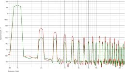
Also out of curiosity, I simulated both distortion and frequency response in Spice.
The following changes have been made to the original schematics to make it possible for today :
2SK190 replaced by 2SK369
2SK186 replaced by 2SK223
2 pairs 2SK1057/2SJ161 replaced by 1 pair Exicon ECW20N20/20P20 (double die)
Feedback network changed to 4.7k/220R/100p
1µH output inductor changed to 3.3µH (for less ringing with 220n load)
The rest are essentially the same as original.
You can decide for yourself whether the performance is good or not.
Easy enough to pay around with load, output amplitude, signal frequency, etc.
Costs nothing in Spice. 😊
Patrick
.
Attachments
@EUVL I follow your posts with interest. I have some of the mosfets used in your simulation. (2sk214/2sk77 and Ecw20n20/20p20) I really want to make this amplifier. Unfortunately, it is very difficult to find jfets. When I look at the stocks; there are audio jfets such as LSK189 LSK389 LSK489 LSK170 2SK208 2SK209 2SK880 2SK2145 JFE2140 and SST404. Can we find something suitable among these?
I am thinking of evaluating my LSK389 and k1058/k162 mosfets in @wahab design.
I am thinking of evaluating my LSK389 and k1058/k162 mosfets in @wahab design.
2SK162 and 2SK223 are both being offered at swap meet.
I don't see the problem.
If you want to find something else, just dig out the datasheets and compare.
Or substitute them in the spice model and see what happens.
Again, the cascode JFETs need to take 70V during power up.
Patrick
I don't see the problem.
If you want to find something else, just dig out the datasheets and compare.
Or substitute them in the spice model and see what happens.
Again, the cascode JFETs need to take 70V during power up.
Patrick
I must admit that I could never manage to use Ltspice. Multisim is not as successful as Ltspice. Discrete designs are a high-level job for me and I have a lot to learn. That's why I definitely need help from those who know this job. I love the sound of jfet and mosfet. The best thing I have done my jfe2140+tda7293 composite feedback amplifier and I think it's one of the best chip amplifier applications I've ever heard. My goal is to do something with fets that can be purchased from mouser and dikikey. Of course, k214/j77 can be supplied from members. I don't want to give up on this amplifier 😊
Thing is that the full fet original schematic has way higher THD and IMD than the version using bipolars
for the VAS, fets simply do not well for this stage, here a simulated comparison at 50W/8R.
@sercan85, try this, limited circuit size for the free version but quite enough and very easy to use :
https://www.simetrix.co.uk/downloads/download-elements.html
for the VAS, fets simply do not well for this stage, here a simulated comparison at 50W/8R.
@sercan85, try this, limited circuit size for the free version but quite enough and very easy to use :
https://www.simetrix.co.uk/downloads/download-elements.html
Attachments
Same applies to 2SK162 and 2SK223.Of course, k214/j77 can be supplied from members.
So what is the problem ?
Patrick
Thanks for offer.Thing is that the full fet original schematic has way higher THD and IMD than the version using bipolars
for the VAS, fets simply do not well for this stage, here a simulated comparison at 50W/8R.
@sercan85, try this, limited circuit size for the free version but quite enough and very easy to use :
https://www.simetrix.co.uk/downloads/download-elements.html
I have lsk389B and K1068/J162 and 10N20/10P20 and I will start your desing.
I download simetrix but I need to read how can I use. But looks simple then ltspice for me.
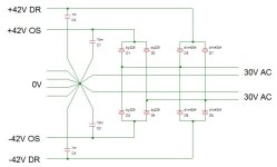
In the meantime here how the power supply should be implemented, there s two rails originating
from the same secondaries, the four diodes D1-D4 can be replaced by a 10-20A/200-400V bridge rectifier
while the four 1N4004, D5-D8, can be replaced by a 2A/200-400V bridge rectifier.
DR stand for driver and these rails should be connected to R17/R18 wich are no more connected to the same
rails as the output stage wich is itself connected to the OS rails of this schematic.
The value of the capacitors is only indicative, instead of 10 000uF for the OS rails you can use 6800uF as well,
for the DR rails the current drained by the driver part is about 25mA, so even 1000uF is hugely overdimensioned
and moreover if it s a dual mono, actualy even 470uF would be way enough for a dual mono.
Also while we re talking of capacitors i ll point that for say +-42V DC it s much better to use 63V caps
than 50V ones as the lifetime of those capacitors is highly dependent not only of the temperature
but also of the effective voltage, typicaly a 63V capacitor has 2x the lifetime, if not more, of a 50V one when
both are used at 42V DC.
Attachments
Just stubled over this amp yesterday, this is definitely going to be my next build. I have 2SK214/2SJ77 , 2SK134/2SJ49 and 2SK1057/2SJ161 in stock . So the only ones im missing is the 2SK190 and 2SK186. So i can build almost all of the original circuit, i also have 2sk117 and 2sk170 in stock.
So the only ones im missing is the 2SK190 and 2SK186. So i can build almost all of the original circuit, i also have 2sk117 and 2sk170 in stock.
K117 can replace K186, though K223 is better with voltage rating.
You need 2x K170 to replace K190.
Alternatives are K162, K369 or K372.
Patrick
Hi
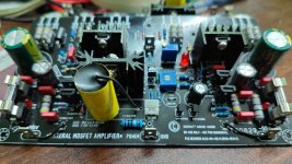
Finally I have found some time to assemble the amplifier board.
If Wahab, Gabor, Alex or any one listening, I have one question.
I would be using three pairs of Mosfets in the output stage and single power supply of 55V to VAS and the output stage. Now what should be the value of the preset that is used to set the Bias for the output transistors? Right now I am using 200Ohms.
Also what should be the maximum value at the preset (before the bias setup) so that current would not damage the output stage. I am planning to set 100ma per Mosfet as bias current.
Kindly suggest.
Ganesh
Attachments
Wich schematic within this thread did you use exactly.?
With three pairs there s no need to bias them at 100mA each, 30mA/pair is way enough for good linearity,
and also reasonable idle power draw given your +-55V rails, i have a lateral fet amp using 3 pairs/channel
and it s biaised even lower at about 20mA/pair.
With three pairs there s no need to bias them at 100mA each, 30mA/pair is way enough for good linearity,
and also reasonable idle power draw given your +-55V rails, i have a lateral fet amp using 3 pairs/channel
and it s biaised even lower at about 20mA/pair.
That should be good as long as it allow to set the curent easily, anyway the two diodes in parralel will limit any wrong doing,
also you could add the 330pf capacitor i mentioned in parralel with R4, 220pF is enough actualy, eventualy the amp
can work without it but it s more cautious to add it as this render the circuit less dependant of the transistors parameters
when it comes to stability.
If you test with +-55V on the first try then put 3-5W 20-50R resistances in serial with the +- supply lines,
or a 40-50W incandescent light bulb in serial with the transformer primary.
Sure. Thankyou Wahab. I shall test the boards in a days' time and come back with the results.
- Home
- Amplifiers
- Solid State
- All Hitachi Lateral FET amplifier for DIY described by Paul Kemble