I don’t want to discourage anyone, but it seems to me that a big part of an amplifiers sound are it’s Vas.
You started well with MOSFETs but are now completely off the reservation.
Is it only due to a lack of said semis? Maybe there exists a solution?
PM if interested.
R
You started well with MOSFETs but are now completely off the reservation.
Is it only due to a lack of said semis? Maybe there exists a solution?
PM if interested.
R
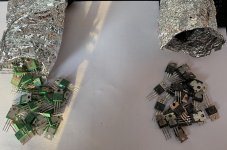
Attachments


TheFinisher, great job!
As I expected, the excitation problem was related to an attempt to replace components. After installing the original products, the problem disappeared. The maximum amplitude when powered by +-36V is 53V at a load of 8.6 Ohm. The quiescent current is 150mA. The amplifier is excellent even with 2SK1058+2Sj162.
As I expected, the excitation problem was related to an attempt to replace components. After installing the original products, the problem disappeared. The maximum amplitude when powered by +-36V is 53V at a load of 8.6 Ohm. The quiescent current is 150mA. The amplifier is excellent even with 2SK1058+2Sj162.
Hi Everyone.
I got the PCB ready and all components including matched LSK170s.
I shall try to assemble it next week and share the results.
Thanks for all the contributors.
Ganesh Laxmanmurthy
I got the PCB ready and all components including matched LSK170s.
I shall try to assemble it next week and share the results.
Thanks for all the contributors.
Ganesh Laxmanmurthy
Hi there all. I agree here that a Vas is very important, special with mosfet outputs because of the large swing. Is it not a problem with the Jfets in future, because of these are obsolete including the Vas mosfets?I don’t want to discourage anyone, but it seems to me that a big part of an amplifiers sound are it’s Vas.
You started well with MOSFETs but are now completely off the reservation.
Is it only due to a lack of said semis? Maybe there exists a solution?
PM if interested.
R
Hello HelgTheFinisher, great job!
As I expected, the excitation problem was related to an attempt to replace components. After installing the original products, the problem disappeared. The maximum amplitude when powered by +-36V is 53V at a load of 8.6 Ohm. The quiescent current is 150mA. The amplifier is excellent even with 2SK1058+2Sj162.
Your amplifier looks more compact and diy friendly... I would lıke to try it but I would like to replacement your transistors, LSK170B=jJFE2140, 2SA1360=KSA1381 or TTA004B,Q. 2SC3423=KSC3503 or TTC004B,Q is it posibble? ı would lıke tou use 42vdc
thanks
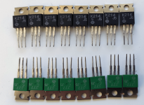
Attachments

Hello Helg
Your amplifier looks more compact and diy friendly... I would lıke to try it but I would like to replacement your transistors, LSK170B=jJFE2140, 2SA1360=KSA1381 or TTA004B,Q. 2SC3423=KSC3503 or TTC004B,Q is it posibble? ı would lıke tou use 42vdc
thanks
While i m here i d like to point that a 330pF cap should be added in parralel with R4 in this schematic
and in almost any other configuration that use such a two stages serial diferentials.
As for your replacement transistors they will work flawlessly, for Q3/Q4 even 2N5551 can be used, for Q7/Q8
the only requirement is the ability to support the full dual rail voltage as well as 0.3-0.5W permanent dissipation,
depending of the supply voltage.
Hi @sercan85, it s in parralel with R4 wich is 2.2k, in the schematic below it s referenced C14.
Also at worst the input fets can be replaced by bipolar devices like the BC550C, 2SC1775(A), 2SC2240, 2SC1845
and by almost any other such low power low noise NPN transistors, the higher bipolars transcondutcance would have to be
compensated by increasing R6/R7 up to 100R.
Also at worst the input fets can be replaced by bipolar devices like the BC550C, 2SC1775(A), 2SC2240, 2SC1845
and by almost any other such low power low noise NPN transistors, the higher bipolars transcondutcance would have to be
compensated by increasing R6/R7 up to 100R.
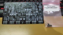
Attachments
Oh sorry i misunderstood. I see now. Thank for share reference schematic.
I dont want to change jfet input. I would like to try Jfe2140 and lsk389-489.
Do you have pcb draw for this schematlcs?
Note:Bias is 150mA for mosfets.
I dont want to change jfet input. I would like to try Jfe2140 and lsk389-489.
Do you have pcb draw for this schematlcs?
Note:Bias is 150mA for mosfets.
The 2SK389 should yield the same amp perfs as the 2SK170.
For Hitachi laterals bias is about 110mA, there s much more to gain by using several devices in parralel than by increasing
the bias of a single pair, not counting that several devices will increase power output if theres common supply rails
for the driving stage and the output devices, wich is the case here.
I would recommend to use a separate 2A rectifier bridge and two 1000-2200uF caps for the driver stages, this way the drivers
will be supplied with the transfo peak voltage even when the output stage supply voltage sag at high power.
I will care your offers. If I decide to buy a lot of LSK170bl what do you recommended Ids current for matched.
Use the best possibly matched and eventualy with the lower Ids, there s some room with VR2 to adjust
averagely matched parts, if there s too much difference between the two closest parts you ll have at hand then
increase R6/R7 to 100R and reduce VR2 total value to 330R, this will extend the correction range.
averagely matched parts, if there s too much difference between the two closest parts you ll have at hand then
increase R6/R7 to 100R and reduce VR2 total value to 330R, this will extend the correction range.
The diodes are used to protect Q2 gate against a faulty condition, they have absolutely no influence
in the NFB itself and for the sound given that they are AC shorted by C4.
It s better to keep them in place, if they are removed then it would be necessary to suppress C4 and connect R13 directly
to the gound but then a DC servo would have to be added.
C4 doesnt need to be anything else than a standard chemical of decent quality.
I just bumped into this, and I am not about to build a Class AB Hitachi design.
But I found it quite interesting how much the circuit has been changed since post #1 in 2012.
Especially when the title said “All Hitachi MOSFET amp”. 😊
Of course the comments at the Paul Kemble webpage is rather tempting :
https://www.angelfire.com/sd/paulkemble/sound7g.html
"For whatever reason, the thing worked very well. I was doing an MSc in the Audio engineering lab under Malcolm Hawksford at Essex University at the time. We knocked some up and were quite taken aback by how good they were …. and there were innumerable commercial clones. It's one of those very simple circuits (like JLH's 10W class A) that somehow just seem to get it right. …. Malcolm actually published a number of AES papers triggered by our investigations of these Balanced Mosfet amps."
This is how I look at the original design in post 1 :
The front end uses a JFET diff pair, based on a pair of Hitachi 2SK190 and cascoded by 2SK186 at 20V gate voltage.
The 2SK190 is a 40V, TO92L, low-noise NJFET with Yfs >37mS.
The 2SK170 only has about half of the Yfs, so you will need 2x (matched) in parallel, or a 2SK369/2SK372 to replace the 2SK190.
Of course you can still get 2SK170 relatively easily, and they are much less sensitive to Vds changes than LSK170.
https://www.diyaudio.com/community/...lsk170-jfet-pairs-grade-b.321649/post-7035859
You can also use 4x matched 2SK209GR in parallel to replace one 2SK190 (or 2x 2SK170) on an adaptor PCB.
https://www.diyaudio.com/community/threads/replacement-for-toshiba-2sk170-2sj74.317563/post-7145633
The diff pair is biased by the 16k resistor (dissipation 0.3W) at 2.25mA each, so that GR grade JFETs will be sufficient.
The 2SK186 is low noise, low capacitance and has a Yfs of 15mS.
The best replacement should be 2SK117.
(The SMD equivalent 2SK209 just does not have enough dissipation to take 100mW.)
But neither the 2SK186 nor the 2SK117 is specified at 70V.
So it is essential that the 70V power rails comes up significantly slower than the 6k8/100µ/20V_Zener at the cascode gate.
The 3k9 drain resistors will get 8.8V at bias.
Since the 2SJ77 has a low Vgs at bias, the second stage will get a total bias of around 24mA, or 12mA per leg.
This is almost exactly at the zero-tempco bias current of those lateral MOSFETs, and the tempco turns negative at higher current. making them self-stabilising.
In addition, they have low but near constant capacitances with Vds.
And they have high enough rated voltage to allow swinging between the +/-70V rails.
I don’t think you can find good replacement MOSFETs for them.
Of course you can try to use bipolar transistors, but it does not resemble the original design anymore.
And they can still be found relatively easily, not ?
The 6k8//33n will drop 80V across it at 12mA bias, and is used to set the drain voltage of the 2SJ77 of that leg, since the 2SK214 drain is tied to its gate.
The 2k2 trimpot on the output leg I find a bit strange.
If the output devices are to be biased at 100mA (also close to their zero tempco point), their combined Vgs is still less than 3V.
That includes the voltage drop of 40mV across the two source resistors.
Again, with 12mA bias, the resistor should more be like 250R than 2.2k.
In any case, I personally would not want to pass 12mA into a trimmer.
So I would want to replace that with a fixed resistor after trimming.
If you cannot get 2SK1057/2SJ161, the Exicon laterals are good replacements :
https://www.diyaudio.com/community/threads/uthaim-just-for-fun.306350/post-5338019
The ratio of transconductances between NMOS and PMOS are about the same (P/N ~ 0.88).
The difference in Vgs is larger than the Hitachi / Renesas laterals, but it is of no importance here, since they are operating simply as source followers.
The 0.2R source resistors are also not necessary if you would increase bias somewhat to 120~150mA, so that the laterals are well into their negative tempco regime.
Laterals are very nice devices for audio.
I would not change them in a circuit purposely so designed.
Happy building,
Patrick
But I found it quite interesting how much the circuit has been changed since post #1 in 2012.
Especially when the title said “All Hitachi MOSFET amp”. 😊
Of course the comments at the Paul Kemble webpage is rather tempting :
https://www.angelfire.com/sd/paulkemble/sound7g.html
"For whatever reason, the thing worked very well. I was doing an MSc in the Audio engineering lab under Malcolm Hawksford at Essex University at the time. We knocked some up and were quite taken aback by how good they were …. and there were innumerable commercial clones. It's one of those very simple circuits (like JLH's 10W class A) that somehow just seem to get it right. …. Malcolm actually published a number of AES papers triggered by our investigations of these Balanced Mosfet amps."
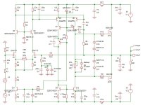
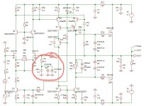
This is how I look at the original design in post 1 :
The front end uses a JFET diff pair, based on a pair of Hitachi 2SK190 and cascoded by 2SK186 at 20V gate voltage.
The 2SK190 is a 40V, TO92L, low-noise NJFET with Yfs >37mS.
The 2SK170 only has about half of the Yfs, so you will need 2x (matched) in parallel, or a 2SK369/2SK372 to replace the 2SK190.
Of course you can still get 2SK170 relatively easily, and they are much less sensitive to Vds changes than LSK170.
https://www.diyaudio.com/community/...lsk170-jfet-pairs-grade-b.321649/post-7035859
You can also use 4x matched 2SK209GR in parallel to replace one 2SK190 (or 2x 2SK170) on an adaptor PCB.
https://www.diyaudio.com/community/threads/replacement-for-toshiba-2sk170-2sj74.317563/post-7145633
The diff pair is biased by the 16k resistor (dissipation 0.3W) at 2.25mA each, so that GR grade JFETs will be sufficient.
The 2SK186 is low noise, low capacitance and has a Yfs of 15mS.
The best replacement should be 2SK117.
(The SMD equivalent 2SK209 just does not have enough dissipation to take 100mW.)
But neither the 2SK186 nor the 2SK117 is specified at 70V.
So it is essential that the 70V power rails comes up significantly slower than the 6k8/100µ/20V_Zener at the cascode gate.
The 3k9 drain resistors will get 8.8V at bias.
Since the 2SJ77 has a low Vgs at bias, the second stage will get a total bias of around 24mA, or 12mA per leg.
This is almost exactly at the zero-tempco bias current of those lateral MOSFETs, and the tempco turns negative at higher current. making them self-stabilising.
In addition, they have low but near constant capacitances with Vds.
And they have high enough rated voltage to allow swinging between the +/-70V rails.
I don’t think you can find good replacement MOSFETs for them.
Of course you can try to use bipolar transistors, but it does not resemble the original design anymore.
And they can still be found relatively easily, not ?
The 6k8//33n will drop 80V across it at 12mA bias, and is used to set the drain voltage of the 2SJ77 of that leg, since the 2SK214 drain is tied to its gate.
The 2k2 trimpot on the output leg I find a bit strange.
If the output devices are to be biased at 100mA (also close to their zero tempco point), their combined Vgs is still less than 3V.
That includes the voltage drop of 40mV across the two source resistors.
Again, with 12mA bias, the resistor should more be like 250R than 2.2k.
In any case, I personally would not want to pass 12mA into a trimmer.
So I would want to replace that with a fixed resistor after trimming.
If you cannot get 2SK1057/2SJ161, the Exicon laterals are good replacements :
https://www.diyaudio.com/community/threads/uthaim-just-for-fun.306350/post-5338019
The ratio of transconductances between NMOS and PMOS are about the same (P/N ~ 0.88).
The difference in Vgs is larger than the Hitachi / Renesas laterals, but it is of no importance here, since they are operating simply as source followers.
The 0.2R source resistors are also not necessary if you would increase bias somewhat to 120~150mA, so that the laterals are well into their negative tempco regime.
Laterals are very nice devices for audio.
I would not change them in a circuit purposely so designed.
Happy building,
Patrick
Last edited:
- Home
- Amplifiers
- Solid State
- All Hitachi Lateral FET amplifier for DIY described by Paul Kemble