If I have forget something please tell me what to do ......or not ,to do.
Alex.
sorry to hear you say it feels like that now
Alex I can't imagine if there is anyone on the forum who would not appreciate your work!
You know who make mistakes- those people who do something!
If I lay all day on the bed that 100% sure there will be no mistake.
I follow many of your art work and all I can say you are great, fast, gifted and very helpful.
Good to have someone like you here at the forum, is a real blessing to us.
The work you done it is not EASY, even do sometimes look a like but is not at all.
And these amplifier board because one sided, and dual PSU one of the most difficult I have done..
I made several PC boards but these needed a lot of focus, attention, energy etc
Please take a day or two and relax after you will feel different.
To be honest you work way to fast and sometimes that make you tired and loose you patient etc
Alex from the bottom of my heart thank you for your help!!!
Greetings Gabor
....... It's the last PCB layout here on this forum , I will not layout anymore ....😡 sorry for that , but for me was enought .....all I done was , layout in wrong way , so I let experts to do this job .
Alex.
Right that continual mods in many designs is time consuming , perhaps
you should wait for all projects to be mature before doing a PCB of your own..😉
Neverless , this last version is great for people who wants no compromise aestheticaly speaking , so thank you for the efforts.
I repost this PCB as there s a missing track for eventual builders.
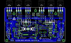
Here is my test board so called "art work"
I upgrade it up to the last mod, I ad the Q20 and the two C12/13 caps.🙂
Since all hand drawn on my computer paint program I do not have silkscreen like Alex who is great and talented with software design.
I did tried one time to use some free software, I didn't succeed so I keep draw my layout by hand.
These is hot iron transfer friendly at least...
Alex design is so beautiful I would pay to get it on a professional made PC board.🙂
Great board as well , Gabor...🙂
I like the compacity of this PCB, yet with all options..
That said , since the laterals have no source resistors , if ever
you want to check the devices individual iddle currents you ll have
to solder only gate and drain on the PCB and solder the sources
from tip of the pins to PCB using 0.22R resistors.
Attachments
Hello
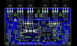
I did listen to your advise and I modded my layout. Now I have Source resisters to.
The PC board got bigger about 8mm but I think it is good to have those resisters
All do I read it degrade the sound a bit but there is a lot of advantage to to have them
Help a bit when not 100% matched the power mosfets. I can measure the bias on each mosfet etc.
So Monday I will go to laser printing to do the PC board to these amp and the Darlington also.
All the components remain the same place accept those now marked on the PC board..
Greetings Gabor
Attachments
Last edited:
....... was obliged with PCB in black and white . Here are files in .pdf form .
Alex.
Alex.
Attachments
Alex thank you very much.
I hope you still be on the forum, you are not just a great layout designer but a great friend to!
We didn't ask you please make these PC board and you came (moved by love) to help on us.
I appreciate that from the bottom of my heart.
I hope we still meet you time to time and you would not give up your hobby.
Over all the PC board lay out came up very nice and great..
Thanks/ Multumesc!
Greetings Gabor
Hello
I would like to know how many people would be interest on PCB GB using the Alex nicely designed layout..
In case you interested please post your interest.
I never org. BG but I did ordered PC boards for the Symasym
Any one who has more experience on PC board order (for good price) or organising a GB please feel free to take charge!
Probably I will use my own layout for the amp, specially if there will be low interest on these project.
I see several Hitachi fet amplifier on the forum now... Probably not the best time when wee came up with these amp.
But again please take a look the sim. result, also the amp was compared with the famous Gold-Mound Min. and on paper well out perform that amp!
The sim result can be found a few page back..
Thanks one more time to wahab for helping me to put such a great circuit together.
Donpetru wee wait on you promised design...
Also if someone want to use my lay out I will give all the necessary help so you can put together these project.
Just let you know I designed several PC board with out any issue.
Again I would advise to use the professionally made Alex layout!!
Greetings Gabor
I think I'll open a new topic whose name will be the name of the new amplifier.Donpetru's variation is an offshoot of this design. So it should stay here as it will be compared with the original circuit. I don't see any harm in his circuit being here and actually think it's better here for evaluating differences.
I don't see how the hexfet's can 'sound' any better but it would be interesting to keep the progress and results within this thread . We would want comparative listening tests . Without that all of this will just be a theoretical exercise. It does make the thread even more interesting ! 😉
I will briefly name the new amplifier DW300 or DWG300 - I'll think about it.
I'm still working on PCB. There will be a single PCB, but something more special. You will see at the right time (ie next week).Hello
Donpetru wee wait on you promised design...
dear alex mm,
you are my friend dont loose your temper plz.stay in the forum and pardon all those who comment on youthanks with best regard masood
you are my friend dont loose your temper plz.stay in the forum and pardon all those who comment on youthanks with best regard masood
Hello
I just printed out the modified layout.
I implemented to the layout Q20 and 2PC capacitor which was added last week or before by wahab.
Also I added Source resisters so I can measure the bias on each mosfet.
Because these mode the PC board size changed a bit.
The right size 176 x 76mm.
Open the last posted layout with the paint program, use page set up 86% and print.
The mean time please get read of all the colored marks on the layout.
I'm more than happy how these layout came out.
Also the Alex layout is more excellent if someone want professional PC boards I advise please use that. If we would org. a GB I would use that to, but I can't wait, I would like to test these amp ASAP.
I thought it will be more interest on these great amp but that will not hold back to go on and build it.
I had 80% the necessary parts for the amplifier.
Also I was interested on the Goldmund clone on that time but a lot of think was very expensive, including the PC boards.
Thank God I didn't wasted my money and energy on that amplifier.
After the sim these amp performance way better, and no expensive parts req.>>>>
A big thank you to wahab!
Tomorrow if the rain stop I want to make the laser copy so I can stat to fabricate my PC boards.
The amp with these rail voltage and biased to 300mA/channel will know more than 100W VMRS..
That is enough for home use with any speakers.
By the way very likely I will have a 39-0-39 600VA transformer for these project, but only available after I tested my amp. Price will be $60 cash..You can ad 2x3M winding for the LC voltage...That is what I did with my transformer to these project.
Greetings Gabor
Also , i replaced the two diodes connected in parralel with C4
by two random transistors wich are used as diodes , each one
having its base connected to its collector , no need to update
your PCB since theses pins can be connected together directly.
Please excuse my ignorant question - but what is the purpose of the two diodes here ? I tried reading the previous posts but may have missed the explanation when the diodes were introduced.. Many thanks!

Please excuse my ignorant question - but what is the purpose of the two diodes here ? I tried reading the previous posts but may have missed the explanation when the diodes were introduced.. Many thanks!
Actually they have no role if the amp work normaly , it s just in case
of failure , if ever the output goes to a rail voltage wether it s due
to a mosfet going short circuit or a rail that would be switched off ,
the consequence would be to have the gate being biaised with
a full rail voltage , hence the diodes to limit the eventual high DC
gate/source voltage.
Gabor, I certainly want to try this amp;Regarding the MSK1058 and the MSJ162 where can I get these or may I use other brands too?
Hello
Those are 2SJ162 & 2SK158... You can get these any distribuitor like Mouser, Digikey etc. On ebay you can find also but I would advise buy those from large distributors to avoid counterfeit chips.
Also you can use Exicon laterals from Profusion..
Greetings Gabor
Those are 2SJ162 & 2SK158... You can get these any distribuitor like Mouser, Digikey etc. On ebay you can find also but I would advise buy those from large distributors to avoid counterfeit chips.
Also you can use Exicon laterals from Profusion..
Greetings Gabor
Actually they have no role if the amp work normaly , it s just in case
of failure , if ever the output goes to a rail voltage wether it s due
to a mosfet going short circuit or a rail that would be switched off ,
the consequence would be to have the gate being biaised with
a full rail voltage , hence the diodes to limit the eventual high DC
gate/source voltage.
I understand now - thank you for the explanation.
I've the 2SJ162 and 2SK1058 from Renesas and for my FetZilla I did use theseHello
Those are 2SJ162 & 2SK158... You can get these any distribuitor like Mouser, Digikey etc. On ebay you can find also but I would advise buy those from large distributors to avoid counterfeit chips.
Also you can use Exicon laterals from Profusion..
Greetings Gabor
ALF08N20V and ALF08P20V
I just printed out the modified layout.
I implemented to the layout Q20 and 2PC capacitor which was added last week or before by wahab.
I made some sims to check the influence of this PCB routing for the most critical tracks at least , and your layout is well done electricaly speaking , it has no negative influence for the amp stability.🙂
I thought it will be more interest on these great amp but that will not hold back to go on and build it.
I had 80% the necessary parts for the amplifier.
The design looks quite complexe and whoever has not great experience in the domain will see it as a difficult to make work while in fact it is supposed to settle at first power on with no other thing to do that setting the bias and eventualy the DC offset.
Also , components prices and availability can be problematic.
Set apart the laterals , wich are not replaceable , the input stage cascodes can be replaced with 2N5551 or BF469/471 if 2SC3423 are not easy to source.
The VAS 2SA992s can be replaced by BC560C but when it comes to the rest of the VAS the 2SA1360/2SC3423 are among the components of choice although BF469/470 or 471/472 would work as well.
The amp with these rail voltage and biased to 300mA/channel will know more than 100W VMRS..
That is enough for home use with any speakers
By the way very likely I will have a 39-0-39 600VA transformer for these project, but only available after I tested my amp.
It should reach this power even if a single +-55V psu is used for both the front end and the power stage.😉
Hi Alex. I hope not to disturb you but i found a small mistake in your beautifull layout: the right side of D3 goes via R0 to E of Q20 but has to go to the base of Q7, this is not connected now........ was obliged with PCB in black and white . Here are files in .pdf form .
Alex.
Regards, Loek
- Home
- Amplifiers
- Solid State
- All Hitachi Lateral FET amplifier for DIY described by Paul Kemble