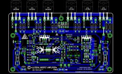
looks even cleaner now
but your ground lines....
actually, I think ground lines should be even bigger sized than the supply rails
looks like theres plenty of empty board space for it now
turn the supply caps , and let the ground line go all the way up to output line
you dont need that long thin ground line for output zobel either, just connect it to ground
make the ground one single line, and as big as possible
its not a digital curcuit, its a high current thingie 😀

Last edited:
Hello
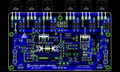
Yes Alex that is much better.
Wahab is right about the mosfet pin. If you can take one more advise.
I would go outside with the PS voltage to the mosfets both side.
I scratched one side like that, that case we could get read of that two jumper..
You have room enough to do that that way. When you invert the mosfet pin 2 & 3 you will gain some room with that to..
Thank you Alex🙂
Greetings Gabor
Attachments

Hi Alex,
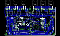
Very nice design.🙂
But I have one suggestion,some wiring points are very close -signal input,
front end power supply, main power ground etc.Kindly avoid that .if you change R33 to left 0f R23A,we will get better looks.
Best regards
joshvi
Very nice design.🙂
But I have one suggestion,some wiring points are very close -signal input,
front end power supply, main power ground etc.Kindly avoid that .if you change R33 to left 0f R23A,we will get better looks.
Best regards
joshvi
Last edited:
missing connection between power ground and signal ground ?
and thus negative speaker connect missing ?
and thus negative speaker connect missing ?
Hello
Wahab C12-1uF what type of capacitor, I guess foil but I ask before I do the mode on my test board
Alex from the old layout you left out C13 that was added later by wahab, it is paralleled with D2 and is a 100nF
Thanks
Greetings Gabor
Wahab C12-1uF what type of capacitor, I guess foil but I ask before I do the mode on my test board
Alex from the old layout you left out C13 that was added later by wahab, it is paralleled with D2 and is a 100nF
Thanks
Greetings Gabor
C12 is 1nf but its value is not critical at all , you can take anything up to 100nF
I took 1nF since this allow using cheap MKP caps as the voltage rating is 200V mini
for this cap.
I took 1nF since this allow using cheap MKP caps as the voltage rating is 200V mini
for this cap.
If I have forget something please tell...
yes, noone responded, but I still think you should connect speaker ground right next to board ground spade
as should ground from frontend aux supply, and signal ground
btw, speaker negative is signal ground just as well as your source
plenty of space for another connect spade(or two) beside the supply ground spade connect
then you can connected all grounds there
it is the right place for it ...especially if main supply caps are further away 😉
No I don't think so , spk negativ must go to star ground , INHO .....yes, I think speaker ng/ground should connect right next to board ground spade, and signal ground
plenty of space for another spade connector beside the supply ground
it is the right place for it 😉
No I don't think so , spk negativ must go to star ground , INHO .....
That s the best solution i think.
Also , there s a 1R (R34) resistor that is missing in the PCB between the signal
and power ground.
Attachments
where do you connect ground from front end aux supply ?
ah !
there s a 1R (R34) resistor that is missing in the PCB between the signal
and power ground.
ah !
where do you connect ground from front end aux supply ?
ah !
Neverless , there s two wires from the PCB that goes to the ground star point ,
one originating from PCB power ground and the other from PCB signal ground.
This resistor is just here for redundancy.
Leach refers to it as the HF connection with reduced impedance due to low inductance of the very short on the PCB routing.
The long routing, if the Main Audio Ground is off the PCB, will inherently have high inductance and thus high impedance to HF.
The long routing, if the Main Audio Ground is off the PCB, will inherently have high inductance and thus high impedance to HF.
Hi,
What do you think of running the thick power ground trace above the drivers?
This would greatly decrease magnetic fields close to small signal circuitry. Further, decoupling caps could even be grouped together in top middle - real small high current loop.
What do you think of running the thick power ground trace above the drivers?
This would greatly decrease magnetic fields close to small signal circuitry. Further, decoupling caps could even be grouped together in top middle - real small high current loop.
Hello
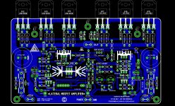
Here is my test board so called "art work"
I upgrade it up to the last mod, I ad the Q20 and the two C12/13 caps.🙂
Since all hand drawn on my computer paint program I do not have silkscreen like Alex who is great and talented with software design.
I did tried one time to use some free software, I didn't succeed so I keep draw my layout by hand.
These is hot iron transfer friendly at least...
Alex design is so beautiful I would pay to get it on a professional made PC board.🙂
In case someone want to go ahead use these as a test boards please open with the paint program, after page set up, chose 90% and print.
If you need the color code I use from the components I already posted but I will help with.
Greetings Gabor
Attachments
- Home
- Amplifiers
- Solid State
- All Hitachi Lateral FET amplifier for DIY described by Paul Kemble