Close coupling a coil in the cathode to a coil in the anode is a good way to implement an oscillator. The oscillation frequency will depend on the phasing of the coils. I have no idea what the aim is here. As we have only just been shown a rough sketch of a small part of the circuit it is difficult to say more.
Close coupling a coil in the cathode to a coil in the anode is a good way to implement an oscillator. The oscillation frequency will depend on the phasing of the coils. I have no idea what the aim is here. As we have only just been shown a rough sketch of a small part of the circuit it is difficult to say more.
The aim is smoothing, it started as a simple LCLC filter. The Lundahl data sheet (and the jacmusic web page below) discusses using the 2 coils on the Lundahl chokes in CMR mode to reduce hum...
Lundahl Transformers - Tube amplifier transformers
in Common Mode Rejection configuration. Schematics will follow in the text, down here. In this configuration, one coil is in the positive lead to the second capacitor, and one on the ground lead to the second capacitor. This will give lowest field radiation coming from the choke. Such good results can not be achieved with lower cost E-Core chokes, and the Lundahl double coil chokes are a major step into the direction of a really hum-free amplifier. Electrically this is calculated as a series connection.
I think I'm getting the forum equivalent of blank looks - has nobody here used Lundahl chokes in CMR mode ? Maybe I've misinterpreted ...
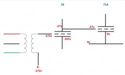
If you invert the voltages on grid and cathode at the 26 perhaps.
Sorry Mona I'm not following why the voltages need to be inverted ... the flow of my thinking was thus ...
- I want the 71A cathode to be at 0v
- With a 27V bias and DC coupled, the 26 Plate must be at -27v
- With 135V across the 26, the 26 Cathode must be at -162v
- With a 10v bias on the 26, the grid must be at -152v
My input is balanced into an input transformer, so I'd apply the -152v there.
Again, just a thought off the top of my head at this point. Has this been tried before ?
Attachments
The aim is smoothing, it started as a simple LCLC filter. <snip> Maybe I've misinterpreted ...
That's not what you showed... look at where the ground is connected vs. the one shown on jacmusic.
Sorry Mona I'm not following why the voltages need to be inverted
The explanation is, I'm a clumsy idiot. Thanks Mona.
Attachments
Sorry it is still unclear to me how you want to supply the tubes, both of them. Can't you draw a complete schematic for the input and driver tubes? Are you using stacked power supplies or just one supply voltage? Why are you using two resistors in the cathode circuit of the 71a?
I assume that you have that CMR choke only at the 2nd filter stage because for L input filter it doesn't work.
I assume that you have that CMR choke only at the 2nd filter stage because for L input filter it doesn't work.
Last edited:
That's not what you showed... look at where the ground is connected vs. the one shown on jacmusic.
... and the penny drops ... the ground is before the return choke, I'd missed that.
Many thanks.
Attachments

The so-called 'CMR' mode (i.e. series aiding) for a dual winding choke makes no difference to ripple/hum suppression. You get the same ripple current going through the same coils in the same direction as for the conventional wiring method. I would expect the same external magnetic field too. The only difference is that you get a little high frequency common-mode rejection too.
To get a lower external field you need to use the common-mode choke wiring. In this case you get good noise rejection but almost no ripple rejection. I fear that someone in Lundahl has confused these two modes.
To get a lower external field you need to use the common-mode choke wiring. In this case you get good noise rejection but almost no ripple rejection. I fear that someone in Lundahl has confused these two modes.
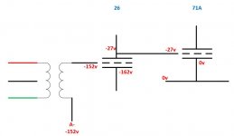
Sorry Mona I'm not following why the voltages need to be inverted ... the flow of my thinking was thus ...
- I want the 71A cathode to be at 0v
- With a 27V bias and DC coupled, the 26 Plate must be at -27v
- With 135V across the 26, the 26 Cathode must be at -162v
- With a 10v bias on the 26, the grid must be at -152v
My input is balanced into an input transformer, so I'd apply the -152v there.
Again, just a thought off the top of my head at this point. Has this been tried before ?
Apart from the mistake already highlighted by Mona, the problem with that supply is that the 26 will have a plate resistor and so on the other end of the resistor the voltage is going to be likely positive or at least less negative than -27V. If the 26 is at regime a bit later than the 71a when you turn on the amplifier it will be really bad for the 71a because its cathode will be grounded, will get its anode voltage and the grid will see a less negative, or even, worse positive voltage. You will have to make the supplies such that the 26 gets going first otherwise....boom!!
Last edited:
Sorry it is still unclear to me how you want to supply the tubes, both of them. Can't you draw a complete schematic for the input and driver tubes? Are you using stacked power supplies or just one supply voltage? Why are you using two resistors in the cathode circuit of the 71a?
I assume that you have that CMR choke only at the 2nd filter stage because for L input filter it doesn't work.
I'll draw the schematic and ask for input in a different thread. Too many different questions being addressed though. My original question was ONLY about how to structure the cathode resistance under a DC coupled valve, and whether all or part of that resistance needed to be bypassed. I'm thinking through the signal section before I put too much work into the PSU.
Another huge drawback of the larger cathode resistor is of course, the larger power dissipated into useless heat and in an output stage.. ugh.
There is another possibility - a second power supply rail. Things will become further complex 🙂
There is another possibility - a second power supply rail. Things will become further complex 🙂
Apart from the mistake already highlighted by Mona, the problem with that supply is that the 26 will have a plate resistor and so on the other end of the resistor the voltage is going to be likely positive or at least less negative than -27V. If the 26 is at regime a bit later than the 71a when you turn on the amplifier it will be really bad for the 71a because its cathode will be grounded, will get its anode voltage and the grid will see a less negative, or even, worse positive voltage. You will have to make the supplies such that the 26 gets going first otherwise....boom!!
Good point - thanks
The so-called 'CMR' mode (i.e. series aiding) for a dual winding choke makes no difference to ripple/hum suppression. You get the same ripple current going through the same coils in the same direction as for the conventional wiring method. I would expect the same external magnetic field too. The only difference is that you get a little high frequency common-mode rejection too.
To get a lower external field you need to use the common-mode choke wiring. In this case you get good noise rejection but almost no ripple rejection. I fear that someone in Lundahl has confused these two modes.
I guess it's the seller at Jacmusic that has confused things....
The so-called 'CMR' mode (i.e. series aiding) for a dual winding choke makes no difference to ripple/hum suppression. You get the same ripple current going through the same coils in the same direction as for the conventional wiring method. I would expect the same external magnetic field too. The only difference is that you get a little high frequency common-mode rejection too.
To get a lower external field you need to use the common-mode choke wiring. In this case you get good noise rejection but almost no ripple rejection. I fear that someone in Lundahl has confused these two modes.
Hmmm. I think I'm back to trying it to see if what Lundahl and jacmusic claim is correct.
http://www.lundahl.se/wp-content/uploads/datasheets/1673.pdf
Another huge drawback of the larger cathode resistor is of course, the larger power dissipated into useless heat and in an output stage.. ugh.
There is another possibility - a second power supply rail. Things will become further complex 🙂
Yeah the thought about a second rail is what made me wonder about structuring things so that the 71A cathode was grounded.
So I did an LCLC version of the Lundahl CMR diagram. Pic 1.
Ive also sketched my current thinking of the amp, without the 45 (pic 2) and with (pic 3).
I think I get it without the 45. As soon as the 45 choke return comes into play surely there's a loop and the 45 psu return current could flow across the 71A choke and vice versa. All sorts of nasties I foresee there.
I'll redo it using both coils in series for the 45.
I've not built a DC coupled design before so just want a little clarification and sense checking please.
I'm building an ALL-DHT power amp.
26 direct to 71A, interstage to 45.
For the 71A, the cathode will be elevated obviously. I'm currently thinking the resistors under the cathode should be separated.
R1 would lift the local ground
R2 would provide the bias
R2 would be bypassed.
Is that correct?
Any option to avoid that cathode bypass cap?
Nice tubes.
Yes many options to avoid (like the plague) large value Rk and also RC bias on the driver tube. What if, for example, you had 71A sitting on top of a VR150, a gyrator plate load to the 26 at 110V... you could run them from a single supply and use CCS for stage isolation. IT will be the weakest link.. I'd look at stacking the output stage on top of the choke loaded driver with some sort of interlock scheme to prevent run-away. 3 stage DC all DHT, and yes, fixed bias output stage (again no RC).
I see the appeal of split rail supply, but I'd want to avoid the input transformer as well.. stacked supplies. One for input/driver and one for OP stage. Why not 2 stage and drive the 45 with 26?... I know that is not your proposition but I dont see a need for the 71A...
Shane
Last edited:
Add a resistor in series wiith the tuning cap. Take a 22uF capacitor and then tune the voltage with the series resistor.
The adwantage is to keep the inrush current peak low. That gives lower EMI which is not wery pleasant.
The adwantage is to keep the inrush current peak low. That gives lower EMI which is not wery pleasant.
22uF is a sufficiently low value that peak currents are likely to be small anyway. This plus a resistor means that essentially you have a somewhat inefficient cap input supply, with LC smoothing.
The best solution to the OP's question is to use solid-state rectifiers, with appropriate steps taken to deal with ringing etc.
The best solution to the OP's question is to use solid-state rectifiers, with appropriate steps taken to deal with ringing etc.
You may have been thinking of a ripple trap technique, where a cap is placed in parallel with the choke to lower 2nd harmonic current transfer through the choke. That 'tuning' effect may change the output DCV a bit, but I don't recall seeing or noting measured levels that would be of any up-front assistance.
- Status
- Not open for further replies.
- Home
- Amplifiers
- Tubes / Valves
- All DHT Circuit Advice