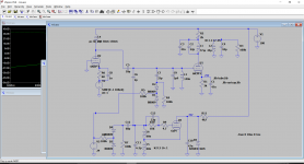
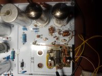
It is not a ratio detector. No tertiary coil, and no stabilising 10uF capacitor to prget cde the limiting function. It is a Foster-Seeley detector with one diode reversed, as in the Dynaco FM3. This does not change its essential nature.
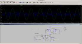
In this picture, green is the IF output, but what is the blue? The linear sum of a signal and the LO as it appears at the grid? Sorry to be such a dummy, but not familiar with this modelling. It must be pretty complete to be able to do modulation. Or is that commonplace now? Cool.
YOS,
Chris
YOS,
Chris
Green is the IF output blue is the grid. The grid conducts a bit. Its only as accurate as the bits you put in there's no board strays at the moment.
... I am contemplating just that, with a JFET/MOSFET front end but retaining the 6N3 front end after this.
The August and September 1987 issues of Radio Electronics magazine describe a simple BCB FM tuner using tracking varactor tuned MOSFET RF amp and mixer ( two tuned circuits ), and varactor tuned LO. They can be downloaded at world radio history ( formerly american radio history ) if you are interested in looking at it for ideas.
Nowadays, one of the Si5351 oscillator kits on the market would be easier, free of drift, and take care of the frequency display for you. Ceramic filters that cover the entire FM broadcast band are available very inexpensively on AliExpress. That might eliminate / reduce the difficulty of making everything track.
I built a simple solid state fm bcb tuner a few years ago and used a prefab FM tuner module to make my life easier. Unfortunately these once common modules are virtually unobtainium now.
Probably will use a SAA1057 synth chip, PIC and bought in display if I get that far. The tracking I will have to work on. The IF stripe and coils work with a small tweak which is a good sign.
The kit is China (of course).
Valve Tube FM Radio Tuner DIY Kit Stereo Receiver Frequency Modulation Board | eBay
The kit is China (of course).
Valve Tube FM Radio Tuner DIY Kit Stereo Receiver Frequency Modulation Board | eBay
The nasty looking one in the eBay picture looks to be a straight line frequency capacitor, which is what you want for easy tuning. The ganged cap in the Fair picture looks to be straight line capacity.
Yep it is, they do say its a nasty AM/FM tuning cap - reused they make this clear. Everything else is new or NOS. The coils have been wound and look very new. That 3 gang looks much better if the synth option does not work. The circuit could do which more image rejection which a third gang would give. Anyway I will try and come up with something in the next few days for comments. I seem to have a magic eye/stripe in the kit but no circuit for it.
Last edited:
https://frank.pocnet.net/sheets/093/6/6J4.pdfI could not find a datasheet for 6K4 and 6J4. Any help much appreciated.
https://frank.pocnet.net/sheets/201/6/6K4.pdf
Here is a 5 gang that *looks* to be a straight line wavelength or frequency cap, but it only has two 10 - 30 pf sections. I'm not sure if you could make the 7 - 27 pF track with the two 10 -30, or not.
5 Section Air Variable Metal Plate Capacitor
76 to 108 MHz bandpass filter - no tuning needed, presumably ...
GFWB3 76 108MHZ Ceramic crystal resonance filter|Replacement Parts & Accessories| - AliExpress
5 Section Air Variable Metal Plate Capacitor
76 to 108 MHz bandpass filter - no tuning needed, presumably ...
GFWB3 76 108MHZ Ceramic crystal resonance filter|Replacement Parts & Accessories| - AliExpress
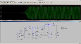
OK I have found that the valve oscillator will work down to 24V or so so this brings is in the range of varicap tuning in terms of voltage. I tried it out and thought it was not working. However the scope does not go above 60MHz. It is working because the grid voltage go negative when oscillating and changes as you put a finger near the coil. I'll have to check whether I can get enough pull with 1-30V tuning. I also don't know whether to use Hi side or LO side local oscillator - not sure what the original circuit does. I could not find a 6c11 spice model so using 6af4.
Yes, in your schematic they're pentodes. How did I miss that? 😱Yes I found these but they appear to be triodes not pentodes.
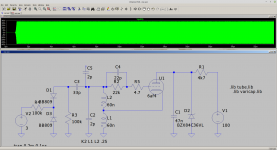
OK the oscillator has been interesting. First problem it is went off at 400MHz rather than 110MHz. Added grid stopped carbon comp resistor 4R7 solves it completely. It may be the inductance here is more important. 22R makes the oscillator difficult to start.
Moved the grid leak resistor so it does not damp the oscillator. If you make it too big (or the cap) the oscillator starts to squeg. LTspice shows this up nicely.
The mixer/oscillator is similar to this:Leak Trough Line Stereo FM Tuner Service Manual and Circuit Diagram | valve-radio.co.uk
The LO is on the high side and looking at the mixer injection this loads the oscillator least. So I will go with this. It also reduces the varicap tuning range which means the voltage across the varicaps can be reduced.
- Home
- Amplifiers
- Tubes / Valves
- Alignment 10.7MHz IF strip
