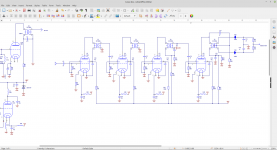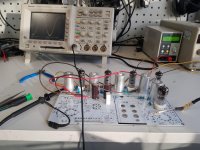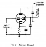
I am building a kit at the moment, and trying to align the IF strip. I've put 10.7MHz into the grid of G2B and working my way along. There are two ferrite slugs for each transformer. T1, T2 and T3 align fine. When I get to T4 there is no signal. I know this is a limiter stage, but the plate of G5 is only at 16V and the screen 48V. This does not look correct. The resistor values look wrong to me. If I remove G5 and connect pin 1 to pin 5 I do get a signal at T4. I could not find a datasheet for 6K4 and 6J4. Any help much appreciated.
First piece of puzzle
6K4 = 6AB6 = EF93
6J4 = 6AU6 = EF94
Looking at the heathkit GR21 to compare - plate resistor looks wrong at 220k.
6K4 = 6AB6 = EF93
6J4 = 6AU6 = EF94
Looking at the heathkit GR21 to compare - plate resistor looks wrong at 220k.
.View attachment 931955
but the plate of G5 is only at 16V and the screen 48V. This does not look correct. The resistor values look wrong to me. If I remove G5 and connect pin 1 to pin 5 I do get a signal at T4. I could not find a datasheet for 6K4 and 6J4. Any help much appreciated.
These gain stages are fixed bias. If the plate on G5 is 16V, that suggests that stage has lost it bias, and running full conduction. If I were building this, I would add 100 ohm plate resistors, such that I could measure the plate current on all 4 gain stages... I gather they all should measure in family, with respect to each other......
Thanks I reduced the 220k to 100k and the plate goes to 40v and the stage works. LTspice gave the same results. The IF strip now has too much gain and oscillates but quietened it down with some 33k across the primaries of a couple of the double coupled tuned circuits. Aligned it and gives a good sine wave with 75KHz deviation. There's a 6ME5 in the kit but nowhere to fit it. That should add a touch of old.
Last edited:
I'd be tempted to make that resistor even lower, maybe they meant 22K? But, an FM tuner kit? How cool is that - had no idea that there are such things anymore.
Can you peak align this guy or is it sweep aligned? Big Fun!
YOS,
Chris
Can you peak align this guy or is it sweep aligned? Big Fun!
YOS,
Chris
I have not built the LO yet. Its originally a valve oscillator, but I would like to make it synthesised - which may means making a JFET oscillator and driving the original one as an amp. The image rejection is rather wanting too. No I've just peak aligned it but used an FM signal to check. The coils seem very well constructed. You have to put a slug inn at each end to align each double coupled circuit. I think the 220k was an attempt to get low gain from this stage but I ended up with nothing! I think they are trying to make it a limiter hence the high valve. One of their finished PCBs does have 220k fitted.
Don't know where your interests lie in experimenting, but you're crazy enough to build an FM tuner, so... I've wondered how much the Marantz 10B scheme of reversed-paralleled small signal diodes for limiting actually affected tuning. IOW, could this just be slipped into an existing design, and call it a day? Inquiring minds want to know.
There's a school of thought that any IF strip that *can* be peak aligned without any wobbles means that it's under-coupled, so nothing else is needed and you're done. I believe this myself, but I'm not smart enough to prove it. Lotsa folks here smarter than me, so maybe some will comment. McIntosh's RIMO (Richard Modaferri) filters are peak aligned, FWIW, but limiting is by exceeding IC diff-input linear range.
All good fortune,
Chris
I have not built the LO yet. Its originally a valve oscillator, but I would like to make it synthesised - which may means making a JFET oscillator and driving the original one as an amp. The image rejection is rather wanting too. No I've just peak aligned it but used an FM signal to check. The coils seem very well constructed. You have to put a slug inn at each end to align each double coupled circuit. I think the 220k was an attempt to get low gain from this stage but I ended up with nothing! I think they are trying to make it a limiter hence the high valve. One of their finished PCBs does have 220k fitted.
How much leeway do you have for customization? IIRC, that setup uses a ratio detector, which is self limiting. Still, if explicit limiting is needed, use a gated beam tube for the job. FWIW, compactrons are available that incorporate the gated beam construct and a small multi-grid power O/P section. The power O/P section might be useful as the pass element in voltage regulating circuitry.
If you find yourself having to do the "AGC dance", incorporating the 6BZ6 into the IF strip might be of value. Remarks have been made that much of the superior sound of "classic" tube FM tuners is directly associated with the transformer coupled IF strip.
As you are already contemplating a synthesized, SS, front end, go "whole hog" and add a dual gate MOSFET TRF stage and solve the "image" rejection problem. I like FETs. Within reason, they can be viewed as heaterless pentodes. 😉 OTOH, BJTs can give you hives and all sorts of other "maladies", especially bad sound.
Attachments

Yep does seem quite mad. I am contemplating just that, with a JFET/MOSFET front end but retaining the 6N3 front end after this. The idea is to build something on a copper clad board where the big tuning gang used to go. Whether I will succeed is another matter. If not your right I could implement some AFC loop with some reverse diodes around the 6c11.
Last edited:
Varicap diode tuning of a triode local oscillator is feasible. Whether or not "synthesizing" is feasible is "above my pay grade".
I was going to use a JFET as the 6c11 generates rather too much voltage for varicap tuning. Could not see how to tame the beast. In simulation L5 has around 160v across it. I think you need quite a big voltage to drive the mixer, so I was going to convert the 6c11 into a LO buffer which should be not impossible on the PCB, and move the coupling to the plate.
Oscillators for classic-era transmitters and classic-era superhet receivers (including FM) are amplitude limited by their grids driven into conduction. Oscillators for hi-fi are limited by an AGC loop to keep everybody on the straight and narrow (and linear). Linearity isn't always needed, or even necessarily wanted - some mixers work better with a square wave from the LO, but limiting doesn't necessarily have to come from either of these. Even a double-diode limiter could do it in the right place.
I've heard of modern FM tuners that have a minimal front end tank for image rejection feeding straight into an A/D. Then some computin'. RF in, audio out. Not much fun for DIY, but amazing if true.
All good fortune, and break a leg,
Chris
I've heard of modern FM tuners that have a minimal front end tank for image rejection feeding straight into an A/D. Then some computin'. RF in, audio out. Not much fun for DIY, but amazing if true.
All good fortune, and break a leg,
Chris
View attachment 931955
I understand the stage is working but the 6J4 calls for a much lower plate resistance than 100k even. The 250vdc source is standard but tube data charts put the plate resistance in the 4.5k to 5.0k range.
I am building a kit at the moment, and trying to align the IF strip. I've put 10.7MHz into the grid of G2B and working my way along. There are two ferrite slugs for each transformer. T1, T2 and T3 align fine. When I get to T4 there is no signal. I know this is a limiter stage, but the plate of G5 is only at 16V and the screen 48V. This does not look correct. The resistor values look wrong to me. If I remove G5 and connect pin 1 to pin 5 I do get a signal at T4. I could not find a datasheet for 6K4 and 6J4. Any help much appreciated.
I need to add to what I said because I wanted to edit but wouldn't let me.
The 100k resistor is allowing the tube conduct but, this is a ratio detector and it's important that the IF tube is run in a more linear part of its curve otherwise it can cut down on sensitivity. I would also try a 22k. The 4.5k to 5k is for a grounded grid circuit. When you dropped the plate by just over half to 100k, that got the tube to conduct and before that it didn't amplify at all. Distortion will lower sensitivity. The spice models can be tricky so you may have to play with that value a bit.
The 100k resistor is allowing the tube conduct but, this is a ratio detector and it's important that the IF tube is run in a more linear part of its curve otherwise it can cut down on sensitivity. I would also try a 22k. The 4.5k to 5k is for a grounded grid circuit. When you dropped the plate by just over half to 100k, that got the tube to conduct and before that it didn't amplify at all. Distortion will lower sensitivity. The spice models can be tricky so you may have to play with that value a bit.
I have a bit too much gain at the moment and have had to put a couple of resistors across the primary plate tank circuits to stop oscillation. I can play with the plate resistor a little later and look at the IF sensitivity - with an FM signal. It seems the second stage is the one prone to oscillation at 10.7MHz.
There's a lot of chip that do that today. The IF, FM and stereo decoding can all be done digitally. Some use zero IF. There are a lot of tricks you can do both in the FM demodulation and MPX that can improve SNR with weak signals. However like valve amps its not what I want to try. It may be I also look at a valve MPX decoder if I can get the thing working.
The old Zen radioman's koan: What do amplifiers do, and oscillators do not?
Oscillate.
Arf! All good fortune,
Chris
Oscillate.
Arf! All good fortune,
Chris
- Home
- Amplifiers
- Tubes / Valves
- Alignment 10.7MHz IF strip
