This is the front end. I went with a JFET as its simple. The LC tank contains both a peak at the wanted and a tracking notch on the image. After a lot of playing in the IF its now working in stereo. Here's some pictures.
.png")

Don't think I will turn it into a finished thing - just complicated.
Don't think I will turn it into a finished thing - just complicated.
It's been very educational for those who rode along with you.
There are many useful pieces of info. to file away. I hope, before death claims me, to try my hand a tuner project.
Thank you!
There are many useful pieces of info. to file away. I hope, before death claims me, to try my hand a tuner project.
Thank you!
Its definitely worth ago. You can synthesize a valve osc as long as the amplitude is controlled. The IF stripe had to have a few 22k across the primary coils to stop it oscillating. The RF comes out very close to LTspice simulation. Something to stimulate the brain rather than another amp. I've got about 1uV input sensitivity and about 65dB image rejection. And it sounds OK.
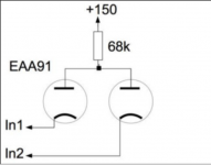
FWIW, I've got a few, tiny, BJT 10.7 MHz. IF trafos on hand that could be used with "parafeed" topology plus wired for step up. Tube B+ would instantly destroy the little things. So, resistively load the IF pentode's plate and cap. couple the signal to the "can".
Unfortunately, I've lost my link to the site in Germany that sells tube specific IF transformers. If a member would provide that URL, my gratitude will be forthcoming.
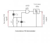
In the realm of "100%" tubed circuitry, I'm thinking coincidence FM detection by a dual vacuum diode AND gate that's fed with a strongly limited signal of the sort produced by the circuitry found in the Harman-Kardon Citation III. Stu Hegeman employed 2 gated beam tubes. CRUSH AM noise!
Unfortunately, I've lost my link to the site in Germany that sells tube specific IF transformers. If a member would provide that URL, my gratitude will be forthcoming.
In the realm of "100%" tubed circuitry, I'm thinking coincidence FM detection by a dual vacuum diode AND gate that's fed with a strongly limited signal of the sort produced by the circuitry found in the Harman-Kardon Citation III. Stu Hegeman employed 2 gated beam tubes. CRUSH AM noise!
Attachments
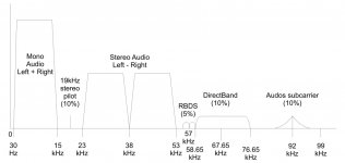
The original china circuit had not enough RF gain/poor image rejection and too much/oscillating IF gain. I don't think you need 5 stages of double coupled tuned circuits. Having three gangs of the cap is the right way forward. I was trying to work around the PCB I bought without hacking it to bits. The coils are nicely made. The FM limiting works well, and I noticed their original ratio detector was a dual diode valve. When you look at the MPX output you realize just have much processing is taking place on the TX it's nearly always 75KHz deviation! I will have a further play to get a bit more RF/mixer gain from the new circuit. The synth is a SAA1057 controlled by a PIC16F677. The idea was to have a display with presets. There's a magic eye in the kit too.
Actually the tubes don't need to run at high voltages. The pentodes you could run the plate at only 60V and get good gain.
I don't think you need 5 stages of double coupled tuned circuits.
The BJT 10.7 MHz. IF "cans" I have are tuned only on 1 side, like this. When used with "sand", the tuned side is connected to the collector electrode and step down occurs. I intend to connect the tuned side to the grid and step up occurs.
The China ones had about 2:1 turns with 10p on the 2 (grid side) and 22p on 1 (plate side). They were just critically coupled with a ferrite slug top and one bottom to tune. I think this is required to get a good bandwidth for stereo. May not be required for mono. I may add a headphone output to the unit. There is a gain stage but no cathode follower which is a shame.
Last edited:
Perhaps a ZVN0545A source follower, like that in the tweaked RCA phono preamp, could solve the buffering problem. FETs and tubes do "play nice" with each other.
Perhaps some of the German IF "cans" and at most 2 pieces of the BJT stuff would work out well. I also plan on using a carefully selected ceramic filter, whose bandwidth disposes of HD garbage and the like, located between the IF/limiter strip and the FM demodulation circuitry. Anything beyond the DSB L-R info. is of no HIFI use.
Perhaps some of the German IF "cans" and at most 2 pieces of the BJT stuff would work out well. I also plan on using a carefully selected ceramic filter, whose bandwidth disposes of HD garbage and the like, located between the IF/limiter strip and the FM demodulation circuitry. Anything beyond the DSB L-R info. is of no HIFI use.
Attachments
Yep good idea may do that as there's no space/mounting for a ECC88.
True but for FM you need about 2 * max deviation + 2 * max mod frequency so ~250KHz BW for stereo. With this BW all will get through.
Audioröhrentechnik Ausgangstrafo Übertrager Bandfilter Spulen Röhren Audio Fassungen 516201 516228 516236 516260 516686 NF-Übertrager Drossel Trafo Hifi Highend
True but for FM you need about 2 * max deviation + 2 * max mod frequency so ~250KHz BW for stereo. With this BW all will get through.
Audioröhrentechnik Ausgangstrafo Übertrager Bandfilter Spulen Röhren Audio Fassungen 516201 516228 516236 516260 516686 NF-Übertrager Drossel Trafo Hifi Highend
Last edited:
Thanks for the link to the German site. That's what I lost. I've replaced the bookmark for the IF transformer page.
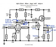
Well I went with an op-amp for the headphone amp - easy. They are 32R and would either need quite a bit of power dissipation or a transformer. The MPX drive to the stereo decoder was too large causing distortion. Now sounds pretty good. Need to improve the coupling/matching into the 6N3 to get the best NF.
- Home
- Amplifiers
- Tubes / Valves
- Alignment 10.7MHz IF strip