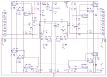
Here is the version I am going to build
Ok, to give this threat again some life and having played around now with Pspice for some time, here it is.
Ratings:
voltage 22,7 volts actual rail voltage at the fets
bias 6,4 amps total bias for one channel
ac current gain 50%
number of fets 12 total number of fets for one channel
Peak current 6,4 amps maximum output current
power 8 Ohms 107,1 watts
power 6 Ohms 122,9 watts
power 5 Ohms 102,4 watts
power 4 Ohms 81,9 watts
power 2 Ohms 41,0 watts
Dissipation 290,56 watts
Dissipation per fet 24,21333333 watts
Transformer secondaries 17,46 volts for 1.3
18,92 volts for 1.2
20,64 volts for 1.1
22,70 volts for 1
Transformer wattage 581,12 watts for factor 2
871,68 watts for factor 3
Source-Resistor 0,47
Frontend with jfets for better sound. I have simulate the frontend with the 9610 and with 2sj109 in comparison and if you get them to the same squarewave-response, the jfet has even a better high-frequency response. In reality the value of the small caps need to be varied, but it shows that the jfet-front-end should work nicely as well.
The change of the feedback-resistor gives as well better high-frequency-response and the change of Ian's resistors from 4,7k to 1k gives better squarewave-response.
Any comments on this (especially from someone who has built it), is highly appreciated.
Best Regards
Attachments
Thanks, Blitz!
Your schematic drawing is beautiful.
Why do the wattage values drop when the speaker impedance is lowered below 6 ohms? I'm planning on building 4 LAB sub horns per channel and they are driven by two 4 ohm speakers each. Because of the acoustic loading on the driver the ohm value will be higher, but I'm still going to need an amp that can play into less than 1 ohm load.
Crazy huh?
LAB horn project webpage
Hi John,
If you go to page 3 of this thread, you’ll find a post by William (Wuffwaff) with an attachment. The attachment is an Excel spreadsheet that allows you to easily change the voltage, current, and number of output devices and see the results in Watts for 4, 6, and 8 Ohms (I also added 16ohms), as well as other loading results. It really is an eye opener.
For example, for a particular rail voltage, if you increase the bias current 1 amp at a time, you find a point where the Watt output becomes Voltage limited (clipping) no matter how much you increase the current beyond that point. The lower the load impedance, the more current you need to output a given Wattage.
Rodd Yamashita
I'm on a Mac,
and I don't have Excel. Bummer.
Would you mind posting a spread sheet with some figures?
and I don't have Excel. Bummer.
Would you mind posting a spread sheet with some figures?
Re: Here is the version I am going to build
Based on my experiments, I think that R47 and 49 are to be 450-500.
JH
Blitz said:ac current gain 50%
Based on my experiments, I think that R47 and 49 are to be 450-500.
JH
I did not mean any sound character, but only technical specification. In the specification of the amp, the ac-current rating is indicated as 50% and powers are estimated based on it. Therefore, I just thought about how to get the 50% value.
Someone could measure the rating after construction of the amp.
JH
Someone could measure the rating after construction of the amp.
JH
Blitz,
the values of the 'macmillian resistors' at 1k seems on the low end. Nelson might have characterized the effects of these resistors on feedback since I remember mentioning something negative about using such low values.
the values of the 'macmillian resistors' at 1k seems on the low end. Nelson might have characterized the effects of these resistors on feedback since I remember mentioning something negative about using such low values.
Re: I'm on a Mac,
I have attached a zip file with 2 CSV spreadsheets. These spreadsheets are the power maps for the Aleph X according to William's calculations for 4 and 8 ohm loads. The maps covers rail voltages from 10 to 60 Volts and bias currents from 1 to 20 Amps.
Enjoy,
Rodd Yamashita
Hi John,carpenter said:and I don't have Excel. Bummer.
Would you mind posting a spread sheet with some figures?
I have attached a zip file with 2 CSV spreadsheets. These spreadsheets are the power maps for the Aleph X according to William's calculations for 4 and 8 ohm loads. The maps covers rail voltages from 10 to 60 Volts and bias currents from 1 to 20 Amps.
Enjoy,
Rodd Yamashita
Attachments
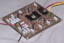
I started a version of the Aleph-X pcb a while back with 2 or 3 devices per bank, as shown in the above schematic. Here is my current board layout with the 12 total devices. If anyone wants my board layout files (I did it in Protel), I can post them. They are done with the schematic editor, and then routed by hand using their utilities, so they can easily be modified to accomidate other's needs.
I was going to make a high powered version, but since playing with lowered power designs, I found out that my speakers don't need more then 50W per channel to be happy.
Here is a picture of my last layout. I have more pictures in my gallery at:
http://brian.darg.net/aleph-x
I made some board for the 8 devices per channel, but never finished it.
--
Brian
Attachments
Thanks Rodd!
I've downloaded the spread sheets and will evaluate them.
Your efforts are very much appreciated.
John
I've downloaded the spread sheets and will evaluate them.
Your efforts are very much appreciated.
John
Grataku, I guess you are referring to this comment:
Well, if rtirion does no have an issue with 1k and the simulator even prefers it, what is the problem then ?
Brian: It would be great to have a pcb. As it becomes a hot amp: Would you separate input and output-part like kristijan did it for the Aleph 2 ?
Best Regards
Posted by Nelson Pass on 07-16-2002 10:41 PM:
I have used as low as 5K without things going to hell.
--------------------------------------------------------------------------------
Posted by SteveG on 07-16-2002 10:44 PM:
Thanks Nelson
--------------------------------------------------------------------------------
Posted by rtirion on 07-16-2002 11:01 PM:
I tried a couple of value's. 10k was the first and least effective.
Used 4,7k and now 1k which I like best.
Today I did a test with an unbalanced input. Works fine, but I like the balanced input better.
Full schematic will be posted end of this week
Well, if rtirion does no have an issue with 1k and the simulator even prefers it, what is the problem then ?
Brian: It would be great to have a pcb. As it becomes a hot amp: Would you separate input and output-part like kristijan did it for the Aleph 2 ?
Best Regards
BrianGT said:Here is my first prototype with 8 devices, in its current state. If desired, we could work out a higher power pcb version, and get a group order together for those desiring more power.
--
Brian
Hi Brian,
Great idea!
Would love to buy a high power version PCB...
Regards,
Lucas.
Brian,
The board looks good. Just a couple of comments, how about some local power supply decoupling capacitors and more space around the mounting holes.
I for one am ready to place my order when you are ready.
Jam
The board looks good. Just a couple of comments, how about some local power supply decoupling capacitors and more space around the mounting holes.
I for one am ready to place my order when you are ready.
Jam
Blitz said:Grataku, I guess you are referring to this comment:
Well, if rtirion does no have an issue with 1k and the simulator even prefers it, what is the problem then ?
I think Nelson prefers to derive conclusion based on measurements rather than simulatons. That's all I am going to say.
There is no problem with that. But if a higher value works fine, what's the reason to put the lower value? Also, I don't think that simulation shows real life DC offset behaviour, which is dependant on many factors, heat and matching being most influencial probably.
1k famous resistor
This 1k value is placed in two real world Aleph-X channels.
I have experimented with 1k, 4.7k and 10k. For my
implementation 1k works best.
Mr. Pass recently reported trying values as low as 2.2k if I
remember correctly.
He also wrote july 2002 in the original Aleph-X thread:
You could try a few values in the circuit, starting with for
instance 4.7k. Then use a lower value.
Measure and listen if it makes a significant difference.
Regards
This 1k value is placed in two real world Aleph-X channels.
I have experimented with 1k, 4.7k and 10k. For my
implementation 1k works best.
Mr. Pass recently reported trying values as low as 2.2k if I
remember correctly.
He also wrote july 2002 in the original Aleph-X thread:
The lower the resistance, the more effective the control
over absolute DC, but then you start depending more
on the common-mode output cancellation to get better
input common mode rejection. I feel it is probably better
to go to higher resistance and use output resistance to
ground to additionally stabilize the absolute DC.
Remember also, the absolute DC offset figure is not
particularly important until it gets so large that it cuts into
the maximum power rating, so a volt or so won't hurt
anything if your inputs are capacitively coupled.
You could try a few values in the circuit, starting with for
instance 4.7k. Then use a lower value.
Measure and listen if it makes a significant difference.
Regards
BrianGT,
Your layout for the Aleph-X with 12 devices looks excellent! The only thing that I would suggest from looking at the photo of your 8 device board, would be to open up the spacing between the paralleled "output" resistors. Also, it would be great to have the pads for the IRFP044 output devices closer to the edge of the board for easier FET mounting. Otherwise I would be MOST interested in a group order of this layout, as would many of the people reading this thread, I suspect!!!
Andrew
Current source
Hello,
When I calculate the ac current gain of the Aleph 4 and of the original Aleph-X I do not understand why there is a difference;
Aleph 4
0.47 / 6 * 1000
-------------------- = 0.508
1.5 / 6 * 619
Aleph X Grollins
0.22 / 2 * 1000
-------------------- = 0.41
0.22 * 1200
Why does the A-X have 0.41 ??? Do I miss something?
Thanks,
Edwin
- Status
- Not open for further replies.
- Home
- Amplifiers
- Pass Labs
- Aleph-X: High-Power Version