Just to avoid any confusion on the VAC ratings above: I am looking in the example only on the transformer-part (AC), William has made some assumptions on voltage drop through Diodes, filtering, transformer regulation to show how much V AC is needed to get 20 V DC. I personally would simulate this with PSU-Designer, as this is the must accurate and simple way to come up with reasonable AC ratings. And you need as well some (4V*10 A perhaps)additional VAC to incorporate the losses.
Best Regards
Best Regards
...and than multiply the whole rating by two (I forgot the current source), so a 480 VAC-Transformer would be the minimum.
As said earlier my personal favorite is this combination ( I have a 6 ohm speaker):
voltage 19,7 volts actual rail voltage at the fets
bias 6,3 amps total bias for one channel
ac current gain 50%
number of fets 12 total number of fets for one channel
Peak current 6,3 amps maximum output current
power 8 Ohms 78,3 watts
power 6 Ohms 104,4 watts
power 5 Ohms 99,2 watts
power 4 Ohms 79,4 watts
power 2 Ohms 39,7 watts
Dissipation 248,22 watts
Dissipation per fet 20,685 watts
Transformer secondaries 15,15 volts for 1.3
16,42 volts for 1.2
17,91 volts for 1.1
19,70 volts for 1
Transformer wattage 496,44 watts for factor 2
744,66 watts for factor 3
Source-Resistor 0,48
which resuts (per channel)
- for pi-filter:
min. (19,7V+4V)*6,3A*2 = 298 VAC
max. (based on current spikes in normal operation):
(19,7+4V)*25A*2=1185 VAC
- for choke-input:
min. (19,7V+4V)*6,3A*2 = 298 VAC
max. (19,7V+4V)*7,5A*2 = 355 VAC
calculated with 2 chokes (15mH) per channel
Best Regards
Current Source
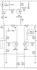
OK, guys, I have just realized that the Version 1.0 has been downloaded about 100 times now, but no one has any comments ? Well than let's have a look together at least at the current source. I changed it now to the version hifizen is suggesting in his beta-version 0.9: So, It is basically Fred's version with connection to the negative rail. Clearly, this is nothing new, but should serve me / you as a wrap-up how the circuit would look like. I guess the resistor values need to be adjusted as we have changed the rail voltage quite a bit. Is there anyone out there with a simulator who give us the right values (wold be great to have it for 22,7V and 19,75V)?
THanks & Best REgards
Attachments
Blitz
The buildout formula I described is an attempt to simplify in a few easily comprehensible steps how to buildout ANY SIZE version of the Aleph-X. I haven't seen the Williams spreadsheet and don't know the formulas used within it so I won't comment on its merit at this time but I suspect there is an error because the power value described under a 2ohm load seems a bit low. There will be some falloff (collapse) as the speaker load falls below the 2.5ohm level but I doubt that it will be as steep as the Williams model presents it. I should remind you that my example was to build out a version that would be stiff to 2.5ohms not 2ohms. It would be interesting to see what the spreadsheet model says the power output would be under a 2.5ohm load which is the example you should have provided if you wanted to highlight a disparity or attempt to invalidate my method.If you feel there are mistakes in the spreadsheet, than shows us where exactly.
Well, my post was an attempt at trying to move the elephants before the mice. Many people want to build bigger than what is practical and the result is usually not as good as something planned to a purpose. I tried to provide some useful perspective since once you build your amp, you will have to live with it and pay the electric bill it generates. If others on this forum are like me, they have their amps on for the better part of the day so this is issue is not insignificant IMHOI am not sure what your message / posting is about.
You are entitled to your opinion. I will tell you that any time the transformer is stressed the possibility of the music signal integrity degenerating increases. I will also tell you that the use of inductance in the power supply is not a panacea and I much prefer a simpler CRC power supply with the capacitance size and quality reducing the ripple but again, this is only my opinion and the readers may form their own as they read through our respective posts.I believe your VA calcs on the transformer are wrong as well
Blitz
Since there seem to be very few comments forthcoming on your high power circuit, I thought I would chip in with something. I suspect that the lack of opinions has more to do with the time of year than any lack of interest.
I've only had a quick look at your circuit but one thing strikes me as indeed it did for Grey's circuit, and that is the inclusion of V1, R11 and V3, R33. I appreciate the need for some form of differential current adjustment but these parts can easily cause more problems than they solve.
Others, including Grey, have mentioned that these parts are not strictly necessary, but I would go further and say they are best removed. If you model this current source in isolation, you will see that the current is not as constant as one would like with variations in voltage across the current source (as opposed to at the intended control point). This has to do with the variation in current in (and hence in the voltage drop across) V1, R11, etc. as the voltage across the entire current source varies. The net effect of this is to make the amplifier more sensitive to DC at the output and hence less easy to trim for zero voltage.
In my own prototype of Grey's circuit, I have also omitted the over current protection parts associated with Q4.
I haven't yet tried a high power version although it is my intention to do so. Hence I cannot yet comment on what really matters other than through simulation.
Ian.
Ian,
Great to have you here and thanks for your comments. Do you see any issues with the current source itself ? HAve you the possibility to simulate the right resistor values for it ?
Nania,
Please don't get me wrong: I appreciate your input, but I truely like to learn from your calcs vs. the calcs other made. You find Williams Spreadsheet in this threat ( page one or two) as an attachment. So, please have a look at it and suggest your corrections.
Your essay on Watts is correct, but it is like someone comes to Mercedes-Dealer and wants a Mercedes, but while being there someone else tells him that in most situations a VW Polo will be equally fast and that he should get a Polo. So, this threat is meant for people who know what they want. Or for all the Aleph 2 Owners / Builders who want a X-Version now. Besides thjis I am with you: I run a triode amp with 25 W SE (VV520V2) and it is awesome ( could have only some more bass control though....).
On the transfomers we are more or less on the same page: If you use a CRC_Filter and don't want any limitations on sonics, go for a 1200VA. Technically less would do so...I missed that comment on your threat. By the way: What issue do you have with choke-input ? With a nice LCRC you have a better ripple rejection than with similar (R)CRC-Filter, need much less VA for the same sonics ( see above), have much less stress ( 7,5 A peaks to 25A peaks) on the diodes etc.
Best Regards
Blitz
I don't know that this is a representative analogy. Saying that building a smaller amp which sounds better than a bigger one is comparing a Polo to Mercedes might be insulting to the Tri-Star if the quality of our aural experience is the goal. You will concede the point that louder is not always better, yes? So why put your resources into a bigger amp if it doesn't help you enjoy the music more? The only reason would be to match it better with a future speaker or listening environment and if you are making that kind of a change, you will most likely improve those parameters rather than worsen them....it is like someone comes to Mercedes-Dealer and wants a Mercedes, but while being there someone else tells him that in most situations a VW Polo will be equally fast and that he should get a Polo.
Outside of the ways it can create more problems than it can solve if implemented poorly (with the wrong value, wrong diameter wire in the coil, etc.) there are the issues related to its physical footprint in the case, its cost and sonically its potential for current limiting/wavering effects and the consequence that has on bass response. To me, these outweigh the 10mV additional noise reduction you may get using a coil.What issue do you have with choke-input ?
endless discussions...
Please go onwards with the calculations,
-but remember that (I think) most of the hundreds of PCB-buyers will use a filterless PSU, atleast for a start,
(and might fine-tune the PSU when everything is in working order/or as a future upgrade/tweak).
What do we then come up with?😕
Arne K
NORWAY
(Need hot amps...it's freezing outside...)😱
OK, Nania I see that we don't come together on choke-input (still I don't get the point with the current though as the delivery should depend creatly on the impedance of your PSU, mainly determined by your last capacitor and real good chokes have not more resistance than the resistor you use anyhow). I guess it won't help that most of the Cellp-Amps by MArk LEvinson use them, and Nelson and many others besides me like chokes as well as stated several times in other threats.
For everybody else interested in this subject, one of the greatest transformer winders building any choke you can think of (his standard are 6 chamber-chokes to avoid resonances, and than he has three even better options on top of that to offer) you will find here:
http://www.ae-europe.nl/ (dutch side, bit very friendly guy talking german and english as well)
For the tube freaks: You will get there OPTs on or surpassing the level of TAngo / Tamura even with amorphous core for a fraction of the price of Tango.
Best Regards
Cobra,
Sorry, our threats where crossing each other. Yes, I am looking for some input o the component values as well.
And I promise this was my last posting on PSUs. BUT BEsides heatsinks the transformer migh be t h e most expensive part in this amp, right ? As the voltage ratings are significantly different between the different filters used ( and you use always one, a simple C is like a pi-Filter from the transformer's point of view...so up to 1200VA needed for 100W), you should know where you want to go to. Fine-Tuning in that respect is only possible if you ordered a special transformer with all the taps for these different scenarios. Very unlikly for most of us.
And now back to the circuit: Any thoughts ?
Blitz
I like a choke too when I can be assured the aforementioned problems are not issues but until then, I will enjoy them much more in other peoples amps than my own.
Even if the coil is built from wire thick enough to mitigate its resistance, the reactance remains a problem. We put caps in parallel to reduce the reactance and then we put in a coil in series to contradict the desired effect? I don't like taking one step back and then having to go two steps forward. Does your hotshot custom coil guy take quiescent current measures? Will he spec to a value and take them back if they fail to meet spec? If so, I may play with some of his coils myself because I would like to see if the "X" circuit levels the playing field to the point of sonic indifference between these two strategies.real good chokes have not more resistance than the resistor you use anyhow
You are in good company. Have you considered that Nelson eschewed the use of a coil in his XA series and that ML might be using them as a cost cutting tool (ie.: in order to get away with using a smaller transformer).I guess it won't help that most of the Cellp-Amps by MArk LEvinson use them, and Nelson and many others besides me like chokes
I like a choke too when I can be assured the aforementioned problems are not issues but until then, I will enjoy them much more in other peoples amps than my own.
Inductors are fine. There's no need to be suspicious of inductors in power supplies. The reason you don't see them in more pieces of commercial equipment is because they're comparatively expensive and bulky. For the average DIY critter those aren't big concerns--especially if you wind your own.
I'd use them more often, but I'm hampered by inability to get decent gauge wire here in SC. Would you believe that the biggest wire I can find in the entire blasted state is 14 ga.? And they act like that's asking for the moon. They'd rather talk about 16 ga. and smaller. I draw the line at mining my own ore, smelting the copper...there's a practical limit to this DIY thing.
<i>Sigh</i>
Grey
GRollins said:Inductors are fine. There's no need to be suspicious of inductors in power supplies. The reason you don't see them in more pieces of commercial equipment is because they're comparatively expensive and bulky. For the average DIY critter those aren't big concerns--especially if you wind your own.
I'd use them more often, but I'm hampered by inability to get decent gauge wire here in SC. Would you believe that the biggest wire I can find in the entire blasted state is 14 ga.? And they act like that's asking for the moon. They'd rather talk about 16 ga. and smaller. I draw the line at mining my own ore, smelting the copper...there's a practical limit to this DIY thing.
<i>Sigh</i>
Grey
Have you tried Home Depot? They have up to 0 gauge...
--
Brian
BrianGT
I've never heard of "0 gauge" wire, if it exists, what was it designed to carry and how would you work it? I'm presuming it's only available in stranded variety. Number "1 gauge" wire was meant to carry mains (25KW loads) and you need to be able to split an apple with your thumbs to work with it, I can't even imagine what "0 wire" would be like.Have you tried Home Depot? They have up to 0 gauge...
I actually considered the possibility of making my own tubes at one point. I've got several old McGraw-Hill textbooks on the nitty-gritty involved, but decided it would be a little-bitty smidgen too far along the diminishing returns curve for me to justify the trouble.
All the wire I've seen at Lowe's/Home Depot is standard house wiring stuff with a plastic jacket. Do they have enamel insulation stuff hidden away somewhere?
I ought to come over and visit. The Atlanta area alone has a more extensive industrial base than the entire state of South Carolina. I could probably pick up all sorts of things over there.
Grey
nania said:Well, it (0 gauge wire) evidently does existlink
Actually you can go quite a bit larger than 0 gauge. Zero gauge is commonly referred to as 1/0 (one-aught), and has a maximum ampacity (as defined by the NEC) of 170A. There are also 2/0 (00) and 4/0 (0000) gauges, with maximum ampacities of 265 and 360A. Beyond that, wire sizes are measured in kcmil (thousands of circular mils), from about 300 and up.
Good luck forming a coil out of it, though. 😉
Sparhawk
Do you know if these wire gauge measures are a recognized ISO (or any other organization) standard? The notion that a wire can be custom made for any application was not unfathomable but I was surprised to learn that "0 gauge" is common enough to put on a wire measuring gauge and even more surprised that a Home Depot would carry it! Your comment about winding a coil with it corroborates my point about how practical it would be to use it. BTW, I have seen a transformer built with "gauge 1" wire and know the man who wound it (my uncle). It was 12"x12"x26" and weighed 320lbs and he was the one who showed me that aforementioned apple trick.
Do you know if these wire gauge measures are a recognized ISO (or any other organization) standard? The notion that a wire can be custom made for any application was not unfathomable but I was surprised to learn that "0 gauge" is common enough to put on a wire measuring gauge and even more surprised that a Home Depot would carry it! Your comment about winding a coil with it corroborates my point about how practical it would be to use it. BTW, I have seen a transformer built with "gauge 1" wire and know the man who wound it (my uncle). It was 12"x12"x26" and weighed 320lbs and he was the one who showed me that aforementioned apple trick.
Nania,
These are American Wire Gauge (AWG) sizes. There are other standards, such as the British SWG (Standard Wire Gauge). Metric sizes are in square millimeters. I don't know if there is an ISO standard.
These sizes are quite common in commercial / industrial applications. Our data centre here has a 600/208V step-down transformer with 2 parallel runs of 500kcmil on the secondary. (For comparison, 1 ga. wire is about 83kcmil).
- Status
- Not open for further replies.
- Home
- Amplifiers
- Pass Labs
- Aleph-X: High-Power Version