Hello
I posted this one in the original Aleph-X thread but nobody cares so I think to post it here
What do you think from the idea to build the mini XA and ad a bunch of source followers behind it to get enough power and if you wish less heat
Rob
I posted this one in the original Aleph-X thread but nobody cares so I think to post it here
What do you think from the idea to build the mini XA and ad a bunch of source followers behind it to get enough power and if you wish less heat
Rob
I'm not clear as to what you mean by mini XA.
If you mean the Mini-A, then yes, you can add more devices if you want. The wattage output will be limited by the rail voltages (and bias), however, not the number of devices. Given the size of the amp as drawn, there's not much point in using more than two pairs of output devices unless you're using really small devices or intend to drive really low impedance loads. Besides, if you go to more than two pairs, you might as well build an Aleph 3.
If you mean the Aleph-X, then again the answer is yes, you can add output devices. That is--at least in part--what this thread is about. Like the Mini-A, ultimately the power will be limited by the rails and bias current.
In either case, increasing the number of output devices will not (by itself) decrease the amount of heat the amp puts out at idle, although you can back off on the bias each device sees and the individual MOSFETs will run a bit cooler.
Adding followers isn't exactly what these amps are about. They're adaptations of Nelson Pass's Aleph current source circuit. As such, you need to view the pairs of output devices as a functional unit--to be added as a set. In the Aleph-X, you'll need to add the same number of output pairs to each side. The original Alephs (including the Mini-A, which I set up to be compatible with the 'real' Alephs) can take one set at a time.
If you want more power than the Mini-A offers, why not build one of the real Alephs? Either the Aleph 3 or the Volksamp 30 offer 30W/ch. As for the Aleph-X...well, it's kinda off by its lonesome. I jumped the gun on availability of official schematics. I've left a trail of bread crumbs for those who want to take a whack at rolling their own, but there's not a full product line, so to speak, just the original 40W version and I'm chipping in a bit on a 100W here in this thread.
Grey
Ok, To give this threat some new life: Here you find a choke-input-configurationn for the previously posted 100W at 6 ohm comfiguration with 19,5V rail voltage and 6,3 A. Obviously you you lower the 26 V of the transformer to 24V-25 V if you would use Schottkys.
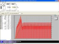
The configuration is by purpose a choke-input which in my experience sounds better and here you see as well why: The peak current for the transformer and the bridge rectifier is with 8A very low compared to a pi-filter. If you want to go with a pi-filter, tha simulate it your self with psu-designer from www.duncanamps.com.
Best Regards
Attachments
Can one use the PCBs...
Hi Folks,
I have been following this thread for a while, but want to ask one thing.
In the normal Aleph-X thread there have been some designs of PCBs by members.
My questions are:
Which board by whom is under production?
Can one still order these PCBs?
Which board would be suitable to use for an Aleph-X high power version?
Any info on this appreciated!
Regards,
Lucas.
Circuit Comments
I see there are still few comments on the actual circuit posted by Blitz so here are a few more of my own.
I'm unsure of the purpose of resistors R6 and R14, presumably these are intended to promote current sharing between the output MOSFETs. I don't think I've seen these in other variations of the Aleph-X and I'm not sure whether they are really required. Including them with have the undersirable effect of reducing the open loop gain. The additional voltage drop will also require the input diff pair current to be increased or R23 increased in value.
Having run a quick simulation, R16, R18, R27 and R30 seem a little large. Using the values suggested will result in a high frequency rolloff starting at 10KHz. These resistors and the value of R23 in conjunction with the gate capacitance of Q2 have the biggest influence on high frequency response.
The power dissipation in Q6 will be quite large (about 312mW) so this may well require a hear sink if a ZVP3306 is used.
I am attaching the circuit I simulated. This is running at the suggested bias (about 1A per output device) and with an input diff pair tail current of 25mA. I've reduced the feedback and input resistors to give a better high frequency response but with the same gain. Not that I would use the LM329 in preference to the zener shown but I do not have a model for the former. I've also reduced the value of R19, R29 to 10k as suggested elsewhere in the Aleph-X thread.
Thoughts?
Ian.
Attachments
Blitz said:Ok, To give this threat some new life: Here you find a choke-input-configurationn for the previously posted 100W at 6 ohm comfiguration with 19,5V rail voltage and 6,3 A. Obviously you you lower the 26 V of the transformer to 24V-25 V if you would use Schottkys.
The configuration is by purpose a choke-input which in my experience sounds better and here you see as well why: The peak current for the transformer and the bridge rectifier is with 8A very low compared to a pi-filter. If you want to go with a pi-filter, tha simulate it your self with psu-designer from www.duncanamps.com.
Best Regards
With such a choke-input you are giving a way a lot of the initial voltage, aren't you?
Doesn't it mean that a lot of heat is dissipated by the first choke?
In what way does such an arrangement sound better?
Is the huge value of the input-choke neccesary?
Thanks for the info!
Regards,
Lucas
Ian,
Thanks for your comments. Let me see, just to get it right:
I understand that you mean the 220K as feedback-resistors (R16 & R30) which are a bit high and the input-resistor of 22K which are R18 & R28 (not R27) right ? In the meantime I have read some comments from people who have built it and that 10K sounds indeed better as it gives more resolution than 22K, so I have changed that. OK, the 220 K resistor should decrease the feedback, but I can change it back to 100K as well. Why did you increased the caps across it ? I believe everbody reported better squarewave with 5pf instead of 10 pf or 18pf.
Are you shure you meant R6 and R14 ? Just to be sure that we mean the same resistor: Which values do they have ? They have been always around...
A 100nF across the zener would be as well not bad I guess. Could you check component values with using a BZX79-6,8 as this lower voltage is what the lm329 would deliver (6,9V) ?
In the Aleph-X threat Nelson gave some hints how the front-end could be improved and pointed to the usage of jfets to get noise down. What are your thoughts on this ? Would it not even sound better to use jfets instead of mosfets in the input ?
Potential candidates would be the P-complements of the well known 2sk179 and 2sk389 (dual type) which stand up to 20mA. Please find the datasheets of the complements here:
http://www.schuro.de/Daten/Japanhalbleiter/2SJ74.pdf
http://www.schuro.de/Daten/Japanhalbleiter/2SJ109.pdf
Some very experienced guys like Mr. Borberly ( www.borbelyaudio.com ) anyhow point out that jfets are the best sounding devices, so combining them with Nelson's / Grey's circuit, well wouldn't this be a Super-XA ?
I used paralleled 2sk170V to get super-quiet current-sources in my preamp as well and sounds great.
Ian, Do you have some Models on these devices to see how much needs to be changed in order to ustilize them in the current source and the differential pair ?
Best Regards
Lucas,
I see that we posted in parallel. To answer your questions:
With such a choke-input you are giving a way a lot of the initial voltage, aren't you?
Yes, but nothing is for free. In a pi-filter you "get" more voltage, but you increase the current rating of the transformer as well.
Doesn't it mean that a lot of heat is dissipated by the first choke?
No, this is not lost energy as we transformer voltage and current only differently than a pi-filter. But the choke should be of good quality not to generate any vibrations.
In what way does such an arrangement sound better?
Instead of up to 45A current peaks, you have only 8 A peak in normal operations, so much less stress and HF-garbage coming from the diodes and transformer. Less technical sounding, less harsh. Less solid-state-sounding.
Is the huge value of the input-choke neccesary?
Yes, maybe you can get a bit down, but I wanted to be on the safe side. Here are dozens of threats how to calculate the min. inductance. Search for choke-input.
Best Regards
Re: Circuit Comments
what is I1, concretely?
Ian Macmillan said:I see there are still few comments on the actual circuit posted by Blitz so here are a few more of my own.
I'm unsure of the purpose of resistors R6 and R14, presumably these are intended to promote current sharing between the output MOSFETs. I don't think I've seen these in other variations of the Aleph-X and I'm not sure whether they are really required. Including them with have the undersirable effect of reducing the open loop gain. The additional voltage drop will also require the input diff pair current to be increased or R23 increased in value.
Having run a quick simulation, R16, R18, R27 and R30 seem a little large. Using the values suggested will result in a high frequency rolloff starting at 10KHz. These resistors and the value of R23 in conjunction with the gate capacitance of Q2 have the biggest influence on high frequency response.
The power dissipation in Q6 will be quite large (about 312mW) so this may well require a hear sink if a ZVP3306 is used.
I am attaching the circuit I simulated. This is running at the suggested bias (about 1A per output device) and with an input diff pair tail current of 25mA. I've reduced the feedback and input resistors to give a better high frequency response but with the same gain. Not that I would use the LM329 in preference to the zener shown but I do not have a model for the former. I've also reduced the value of R19, R29 to 10k as suggested elsewhere in the Aleph-X thread.
Thoughts?
Ian.
what is I1, concretely?
Blitz,
We seem to be in agreement regarding feedback and input resistors. I used 18pf across the feedback resistors because this gives the flatest frequency response according to the simulator (which may or may not be the case in practice). If others have measured a real life circuit and found 5pf to be better than that is the value to go for.
The resistors I was questioning are marked as R6 and R41 in your schematic and are 0.47R (or 0.68R in my version). I don't think I've seen these used in the gain stage although obviously they are required as part of the Aleph current source.
Sorry, didn't mean to omit the cap across the zener.
Not sure about the use of JFETs for the front end in this application. They are better in low noise circuits for sure, but in this application they have less transconductance and hence may lead to a higher overall distortion figure. Also the maximum disspitation of 2SK389 is about 200mW so operation at the required current is not likely to be possible without paralleling several. Lower current means larger values for R23 which will lead to a poorer high frequency response. I'll try playing around with these on the simulator but I'm not that hopeful.
Bricolo,
I'd be happy to give you a concrete value for I1 if you tell me to which current this corresponds.
Ian.
Current limiting
Something else to consider when deciding on how much bias is required for a given application. Simulation shows this circuit to have poor performance when current limited, i.e. insufficient current for the load impedance. The waveform becomes severely distored, unlike the typical clipping displayed due to voltage limiting.
I would be interested to know whether anybody has made measurments of this condition with a real circuit since it may just be an artifact of the simulator. Unfortunately I do not have the equipment to make the measurements on my own circuit.
If this is a real effect, then more bias may be required than at first envisaged (for low impedance loads).
Finally, I seem to recall someone giving a rule of thumb for how much current from the driver is required per output MOSFET in order to drive the capacitance of the latter. Unfortunately I cannot recall the value. This may be another significant factor when cosidering a JFET front end. Can anyone help me out here?
Ian.
Jfet front end
I'm in agreement that a jfet front end for the Aleph is a tricky endeavore. At least two pairs would need to a paralelleled and a high transconductance type from the violet bias group would be reguired like the 2SJ109 or matched 2SJ74s. The V (violet bais group are very hard to find. A mosfet follower stage between the front end with IRF610s might allow a Jfet front end and would give another 3 or 4 volts and less capacitance across the required larger value drain load resistor for the front end.
An N jfet front end would require P channel mosfets for the out put gain stage. You don't even want to go there!
The 2SJ77 might make a very good current source transistor for the front end and allow easier heat sinking than the Zetex type that has been dissicussed.
http://ezphysics.nchu.edu.tw/prophys/ael/File/Datasheet/sj77e2.pdf
It is nice to the black and white of detailed disscuss of specific approaches to this design rather the generalization in the grey areas of generality that has become much to prevalent by some posters.
Loren
We use JFET inputs in all the X products except the
X1000, X600 and the XA's.
I've built a number of Alephs and other 2 stage circuits,
complementary and not, with JFET diff pair inputs and they
work very well, but as the transconductance is quite low
they tend not to have enough feedback for very low
distortion. But then we don't necessarily judge an amp
on that basis, do we?
In any case, you can pretty much pop them in, adjusting the
values of the current source and load resistance to fit the
part.
Hmmm....If I recall okay I`ve seen a picture of a X350 in a German Hifi magazine review which showed MOS-Fet`s for the front-end.originally posted by Nelson Pass
We use JFET inputs in all the X products except the X1000, X600 and the XA's.
As all the front-end transistors were in TO-220 cases they must have been MOS-Fet`s😕
Warning about supply voltage and bias current calculations
One thing I want to add:
when you calculate the output power of your aleph-x, either using formulas or an excell file, for 2,4,6,8 ... ohms, you should better make a graph with the power function to the load impedance
I've seen many of you who have made calculations for their speakers, in example going from 6 to 8 ohms, telling:
so, with X volts and Y amps, i've got:
98W in 8 ohms
97.3W in 6 ohms
but what is between 8 and 6 ohms? certainly not a straigh line, but a peak!
I've made a graph, using berekening1.xls, and the power/impedance is shown at the bottom of my post.
You see that at first you have a current limited mode, then a peak, and after that, a voltage limited mode
Attachments
Power limits
Interesting graph.
I would be interested in whether anyone has conducted any listening tests of this circuit under different limiting conditions. For example, does the amp sound different when current limted as opposed to voltage limited. I'm curious as simulations show some pretty bizzare behaviour when current limited.
BTW, I realise that no sane person would intentionally operate their amplifier in a severe limiting condition (not good for sound quality nor speaker life!) but even so, under some music conditions an amplifier may well approach or reach such limits. I guess the real question here is that if we have to run near one or other limit, which is to be preferred?
Ian.
I think that running it far from any kind of limitation is the best
Tell me if I'm wrong, but if you run it in non limited mode, you'll have a flat top for the curve I've shown
Am I right?
If I am, that's the way we should run our amps
Tell me if I'm wrong, but if you run it in non limited mode, you'll have a flat top for the curve I've shown
Am I right?
If I am, that's the way we should run our amps
Current X350's use JFETs.cocolino said:Hmmm....If I recall okay I`ve seen a picture of a X350 in a German Hifi magazine review which showed MOS-Fet`s for the front-end.
As all the front-end transistors were in TO-220 cases they must have been MOS-Fet`s😕
You will not get a flat top to speak of. Pick your voltage andBricolo said:I think that running it far from any kind of limitation is the best
Tell me if I'm wrong, but if you run it in non limited mode, you'll have a flat top for the curve I've shown
Am I right?
If I am, that's the way we should run our amps
bias to get the peak figure you want, and welcome to the
world of single-ended Class A.
Nelson Pass said:
You will not get a flat top to speak of. Pick your voltage and
bias to get the peak figure you want, and welcome to the
world of single-ended Class A.

do you mean that with a smaller input voltage, I'll have the same curve, but with lower power?
- Status
- Not open for further replies.
- Home
- Amplifiers
- Pass Labs
- Aleph-X: High-Power Version