I used a traditional single ended speaker protection circuit. I powered it from a separate small transformer or if you have a separate winding on your power transformer. Leave the 0V of the protection circuit ungrounded. You can connect the 0V and the DC sense input of your protection circuit directly across the (+) and (-) outputs of your amplifier and it will work normally.
I shall check and publish the improved version if I can find time.
It has been checked by SPICE simulation but not by built.
If you wish to try, we'll provide a free PCB for you (you pay P&P only).
But I have no time to nurse you right now, so you are on your own.
It is much better to use a proper diff-pair to do this than a floating protection Gnd, IMHO.
Patrick
It has been checked by SPICE simulation but not by built.
If you wish to try, we'll provide a free PCB for you (you pay P&P only).
But I have no time to nurse you right now, so you are on your own.
It is much better to use a proper diff-pair to do this than a floating protection Gnd, IMHO.
Patrick
You can follow it here further :
http://www.diyaudio.com/forums/pass...r-amplifier-balanced-outputs.html#post3916217
Patrick
http://www.diyaudio.com/forums/pass...r-amplifier-balanced-outputs.html#post3916217
Patrick
Speaker protection
Just wanted to say thank you to those that responded.
I've printed the Xen Audio circuit and I'll order up any parts I don't already have tomorrow.
Just wanted to say thank you to those that responded.
I've printed the Xen Audio circuit and I'll order up any parts I don't already have tomorrow.
Suggest you wait till I publish Version 2 before you order anything.
I'll see if we can do so in the next 24 hours (no promise).
It is basically an upside down version of V1 plus a few refinements.
You can then decide which one is better for your application.
If you want to scratch build V2 then you can use 2SK170 or better still 2SK117 to replace 2SK209.
They do want to be matched to say 10% Idss.
V1 I used to scratch build P2P, so not difficult at all.
If there are questions please refer to the other thread in post #2443.
We probably shall only support V2 in the future.
Patrick
Last edited:
Speaker protection
Thank you for posting details of the V2 versionof the speaker protection circuit.
You mentioned previously that there would be a PCB available for the V2 - how can I get some of these?
Can you clarify for me please - the junctions of c1/r7 and c2/r8 - are connected to ground?
Thank you for posting details of the V2 versionof the speaker protection circuit.
You mentioned previously that there would be a PCB available for the V2 - how can I get some of these?
Can you clarify for me please - the junctions of c1/r7 and c2/r8 - are connected to ground?
Noise?
I built one in reverse mode (2SK389 as input, BC560 and IRFP9240 [single], +-15 V). One channel is working, but on the other I have problems:
I get sound, trying with speaker between OUT and ground, one half sounds fine, but on the other there is white noise, weak sound and the offset is different from the other half. On this half the offset starts with +7V and only after 3-5 seconds suddenly goes down to about zero. Any guess about a reason? I exchanged all power FETs and PNPs, can't find a difference to other half/channel ...
Zeners? Capacitors?
Last edited:
Post your schematic annotated with measured DC voltages for the problem channel. Comparing the half that works to the side that doesn't will help you identify the problem.
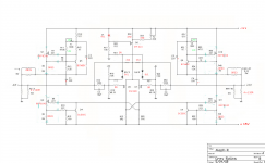
This is the schematic. Red my changes. Green is "power saving mode" which I adjust to 0.9 V across R6 and R41.
In this mode the "good" half starts at 0.5 V output vs. ground and "switches" to -0.5 V after about 5 seconds, "bad" half starts at 2.1 V and goes down to -0.9 V. "Good" half sounds ok vs. ground, "bad" half has noise and bad sound.
Voltages with both inputs at ground.
I have the same problems in high power mode so I wanted to test like this, I don't have to mount/unmount from heat sink every time.
Also I have big hum at the output if I don't connect the input's ground, which I don't have on the other channel
-- OK! I have a big difference in input resistance to ground 40k vs 18k
Attachments
Last edited:
How does it work with the proper value?
If still not working, annotate the schematic with measured voltages. You might want to replace the 0R gate stoppers in the input with 221R or so to help prevent oscillation.
If still not working, annotate the schematic with measured voltages. You might want to replace the 0R gate stoppers in the input with 221R or so to help prevent oscillation.
Glad you sorted it out. Jfets have the same input capacitance/trace inductance potential problems as mosfets. The DIYAudio store AJ boards have provisions for gate stoppers, but most leave them out. If you are oscillating, you can add gate stoppers.
My first thought after reading your description of the sonic differences between the channels is that you have a ground loop. I noticed that you removed R21. That resistor is typically used to damp ground currents between the channels. This can in turn lead to oscillations, usually stronger in one channel IME.
Graeme
Graeme
I was missing highs in the old 9610 input so wanted to try without gatestoppers ...
Hm R21 only comes into play if you have overvoltage at input?
Hm R21 only comes into play if you have overvoltage at input?
Glad you sorted it out. Jfets have the same input capacitance/trace inductance potential problems as mosfets. The DIYAudio store AJ boards have provisions for gate stoppers, but most leave them out. If you are oscillating, you can add gate stoppers.
I hope he's not oscillating

I have one of my Aleph-x's on the bench - with a scope probe on each output and ground I'm seeing sine waves of differing amplitudes (about 2v difference). I am driving the amplifier single ended (capacitor to ground on the inverting input) but have noticed the same issue previously when using a DRV134 single ended to balanced convertor.
I've searched the forums for "Asymmetrical Aleph-X" and found a couple of references to the issue. As a result I tried changing the resistors from the output nodes to ground from 34 ohms to 68 ohms and that has made a small difference to the overall amplitude but the relative difference remains similar. Another suggestion was to raise the value of the "Macmillan" resistors (mine were 4.7K so I increased them to 10k) - that has made no difference to the relative amplitudes (but has affected the output waveform, was a sinewave, now a sinewave with a dip at the top (looks like an M) instead of peaking properly.
Any helpful suggestions would be appreciated.
BTW - I did ask about this some time ago and was advised to check the matching of the input diff pair - that's also been done, hence running out of idea's....
- Home
- Amplifiers
- Pass Labs
- Aleph-X builder's thread