Terry,
I mean C9 and C10 (ca. 3n3-4n7) and C2 and C4 (5-10pF).
62° after a day is not that hot for the heatsinks, transformerwindings are specified for 105°C or 130°C and can become very hot to touch. Here the high ambient temperature will be part of the problem. Maybe you can give it some cooling like holes in the bottom of the case?
William
wuffwaff said:Terry,
I mean C9 and C10 (ca. 3n3-4n7) and C2 and C4 (5-10pF).
62° after a day is not that hot for the heatsinks, transformerwindings are specified for 105°C or 130°C and can become very hot to touch. Here the high ambient temperature will be part of the problem. Maybe you can give it some cooling like holes in the bottom of the case?
William
Hi William,
Yes, I installed the caps in those places. As a matter of fact, I installed all of the caps. I will have to look to remember which values I used, but I'm pretty sure I was within those ranges. I did some checking last night with my heat guage and the hottest things were the R1 and R4. They were 108C. I used 3w 62ohm there. Perhaps I should increase the wattage for those. My absolute offset was less the 200mV. That's all they were dropping. I'm not sure why they were so hot.
Be carefull with that transformer if it over heats it could cause a dead short or the full ac line into your amplifier.. Maybe get a transformer over rated for this .
This transformer is rated at 1.2kV for 4X12V. That should give me 600mV per channel at 12-0-12VAC. That's more than a lot of other folks reported using.
Terry,
Not to scare you, but if your transformer gets that hot and your sinks get that hot your going to have to bias the amp down before you have a fire. This is no joke. If your transformer gets that hot eventually it will fail and cause all sorts of fireworks. I certainly would not leave it unattended if its running that hot. Larger sinks and a larger toroidal may not be a bad investment.
Yes, I think I will bias it down some. That is what I meant when I said I would change out the source resistors for 0R22. I'm running 0R15 right now.
Blessings, Terry
Hi Terry,
if R1 and R4 are so hot something must be wrong! Are R44, R45 just as hot?
At 200mV Abs. DC the should be dissipating 0,2x0,2/62= 0,0006Watts.
I´m affraid your amp is oscillating
Please try to check this with your newly aquired scope.
William
if R1 and R4 are so hot something must be wrong! Are R44, R45 just as hot?
At 200mV Abs. DC the should be dissipating 0,2x0,2/62= 0,0006Watts.
I´m affraid your amp is oscillating
Please try to check this with your newly aquired scope.
William
wuffwaff said:Hi Terry,
if R1 and R4 are so hot something must be wrong! Are R44, R45 just as hot?
At 200mV Abs. DC the should be dissipating 0,2x0,2/62= 0,0006Watts.
I´m affraid your amp is oscillating
Please try to check this with your newly aquired scope.
William
I would love to check that. Unfortunately, I don't have a clue how to operate this scope. I keep hoping that someone will give me some step by step instruction as to how to hook it up and what to set everything at. So far, the instruction I've received requires some knowledge on my part, which sadly, doesn't exist.🙁
I suspected that R1&4 shouldn't be so hot with only that much drop. That is why I mentioned it. I can't be positive that those are the ones for sure since it is pretty clustered right there but I pretty sure those are what is hot. I'm not touching them with my finger to find out.

The ambient temerature in the room was pretty high after this amp running in it all night and day. Probably 80-85F I bet. I won't need a heater in there this winter. 😀
Anyway, If you're willing to give me some bone-head instruction on the scope, I will be forever in your debt.
Blessings, Terry
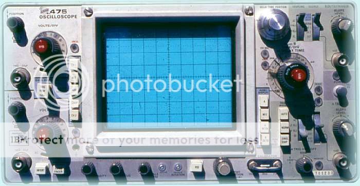
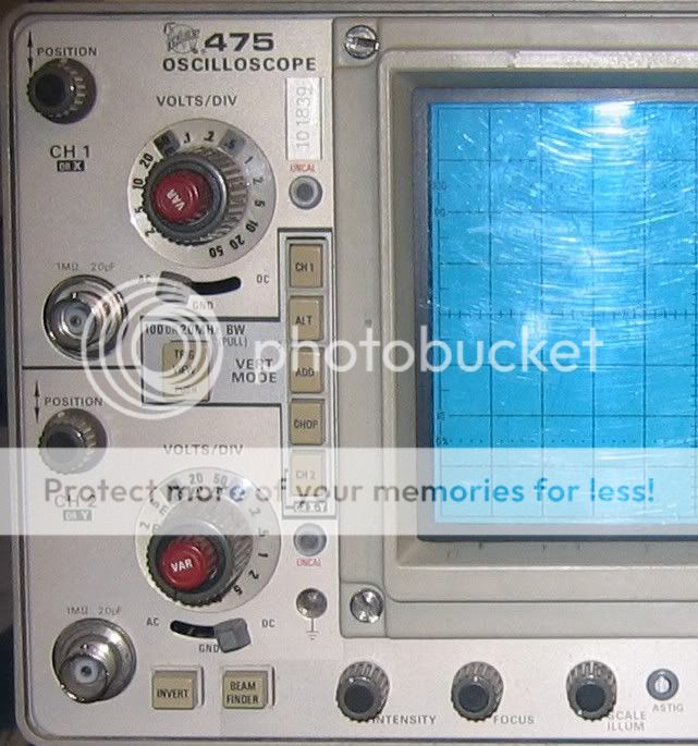
Terry, please post a picture of that scope's buttons arsenal.still4given said:
Anyway, If you're willing to give me some bone-head instruction on the scope, I will be forever in your debt.
What boards did you use? I'm too lazy to go through the tread.
/Hugo 🙂
Netlist said:
Terry, please post a picture of that scope's buttons arsenal.
What boards did you use? I'm too lazy to go through the tread.
/Hugo 🙂
How's this?
I used the HiFiZen boards.
Blessings, Terry
Terry,
The HifiZen boards tend to oscillate, I believe this was stated before. Do add C9 and C10 as William said. I recall however, in the big AlephX thread, Nelson saying what was posted in the AlephX WIKI under 'More unsorted -> Unconfirmed: 1nF
I know it's there somewhere to be confirmed, only I can't find it...
Edit:...I should read before I post. Sorry.
I'll try to help on the scope later.
/Hugo 🙂
It must be my eyes or the picture but I can't really determine what the buttons are for. There would be too much 'probably's' in my response. 🙂
I'll look if I can find a better picture on the net.
Assuming it's a Tek, I can download the manual but need the serial number.
/Hugo
I'll look if I can find a better picture on the net.
Assuming it's a Tek, I can download the manual but need the serial number.
/Hugo
Netlist said:It must be my eyes or the picture but I can't really determine what the buttons are for. There would be too much 'probably's' in my response. 🙂
I'll look if I can find a better picture on the net.
Assuming it's a Tek, I can download the manual but need the serial number.
/Hugo
Hi Hugo,
I downloaded it here.
http://www.slack.com/pdf/Tek475A-DM44-op.pdf#search=Tek475ADM44op
I'll try to remember to take a clear picture of mine when I get home.
Blessings, Terry
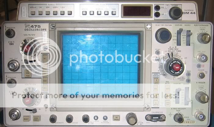
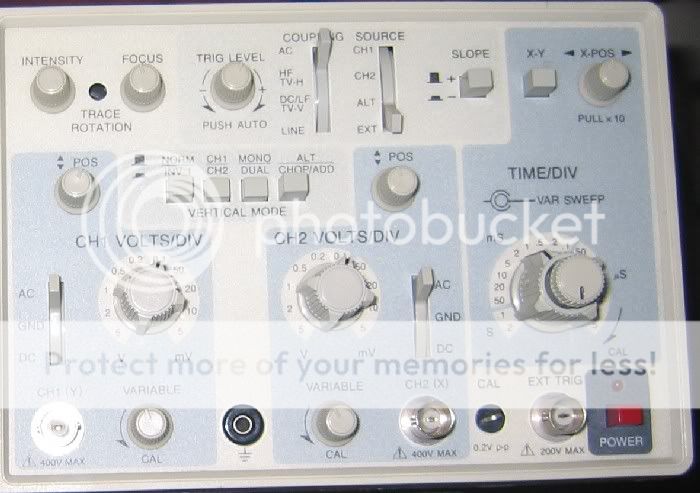
OK I took some pictures of my scope.
Here's the Tek
And here is a BK scope that a good friend gave me yesterday. 😀
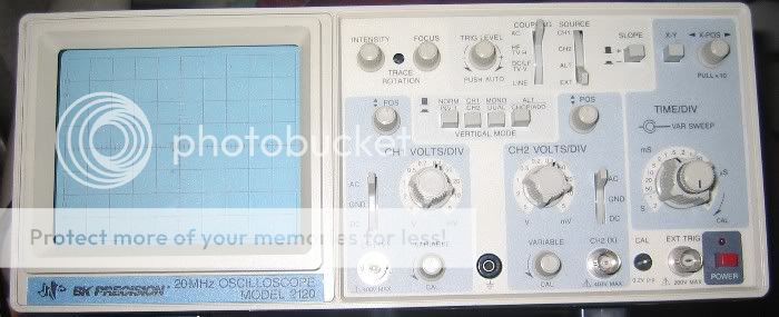
I would be happy with instructions for either one or both.
Blessings, Terry
Here's the Tek
And here is a BK scope that a good friend gave me yesterday. 😀
I would be happy with instructions for either one or both.
Blessings, Terry
Terry,
Switch on the scope and see if you get a trace on the screen. Adjust for a nice line just in the middle with Intensity, Focus and Position.
It looks like most buttons are in the correct position to perform a first measuring.
Basically, you stick one probe to CH1 input and connect it to the +out of the amp. Ground wire goes to ground of the amplifier. Never connect the ground wire to +out or –out or anything else in the amp except ground.
When feeding signal to the amp at moderate volume you should be able to see something on the screen that looks like a rhythmic pattern, going up and down with the beat/volume of the music. Correct for a more or less full screen pattern with the Volts/DIV knob.
More on measuring oscillation in the next post. Tell us if you managed to make it this far.
/Hugo
Hi Hugo
Yes, I managed to get the signal visually. It is represented with three traces AFAICS. Moves way to fast for me to make anything out of it.
Blessings, Terry
Yes, I managed to get the signal visually. It is represented with three traces AFAICS. Moves way to fast for me to make anything out of it.
Blessings, Terry
Terry,
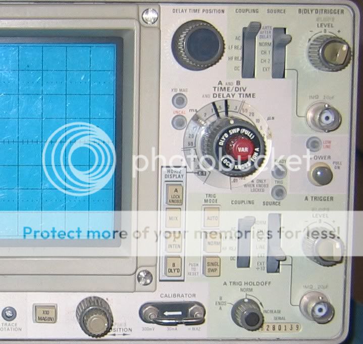
Now, feed the amp with a sine wave of say 1Khz and adjust Volts/DIV for proper amplitude and Time/DIV for a full or double view of the sine wave. Play around a bit with both knobs, vary the frequencies to something like 10Khz, lower the input signal and adjust again so you get the basic feeling.
Next step is to short the input of the amp to ground, no signal cable attached and a dummy load or an old speaker at the output.
Look at the scope and increase the sensitivity (Volt/DIV turned to the left) and the Time/DIV up to the µS range. If all is well, you should see a line just as if the scope were not connected to the amp. This is the ideal situation. Of course you will see some hum or noise but if the amp oscillates you will notice a high frequencies pattern, far higher than the audible range.
That's it for now, let us know.
/Hugo
Hi Hugo,
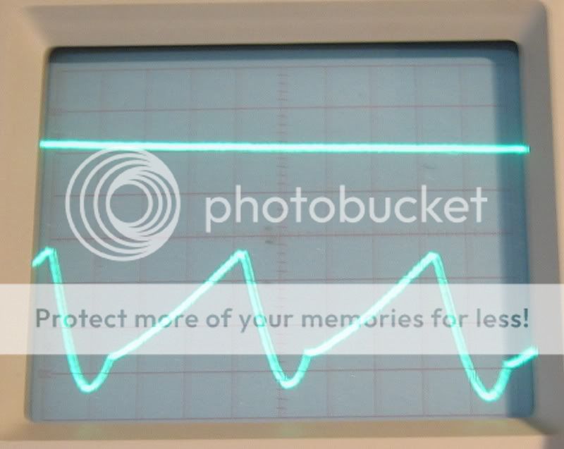
OK, I didn't have a sine wav yet but I hooked up the scope with one probe on each side and the grounds to chassis. With the input shorted this is a picture of what I see.
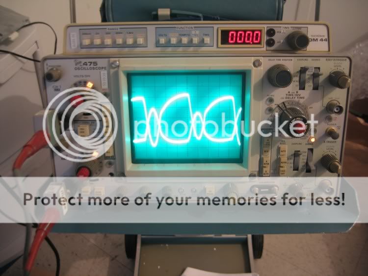
Obviously something is going on. If I switch the amp off I get two straight lines.
So if I do have oscillation, how do I go about getting rid of it?
Blessings, Terry
OK, I didn't have a sine wav yet but I hooked up the scope with one probe on each side and the grounds to chassis. With the input shorted this is a picture of what I see.
Obviously something is going on. If I switch the amp off I get two straight lines.
So if I do have oscillation, how do I go about getting rid of it?
Blessings, Terry
Terry,
What you see is power supply ripple. If your vertical attenuator (Volt/DIV) knob is at 0.1 the ripple is too high.
To see if the amp is oscillating you need to turn the time base (Time/DIV) up towards the µS range. At this time it is in the range were you are able to see the 50-100Hz range.
/Hugo
What you see is power supply ripple. If your vertical attenuator (Volt/DIV) knob is at 0.1 the ripple is too high.
To see if the amp is oscillating you need to turn the time base (Time/DIV) up towards the µS range. At this time it is in the range were you are able to see the 50-100Hz range.
/Hugo
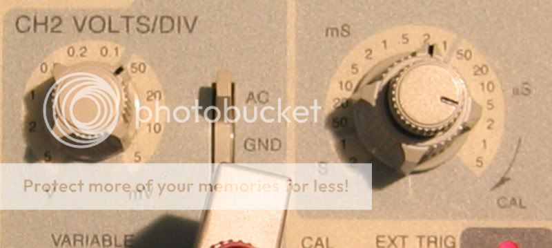
Hi Hugo,
Let me show some more pics if I may.
Here is with these settings. The knob on the right is the TIME/DIV setting. It is set at .2mS
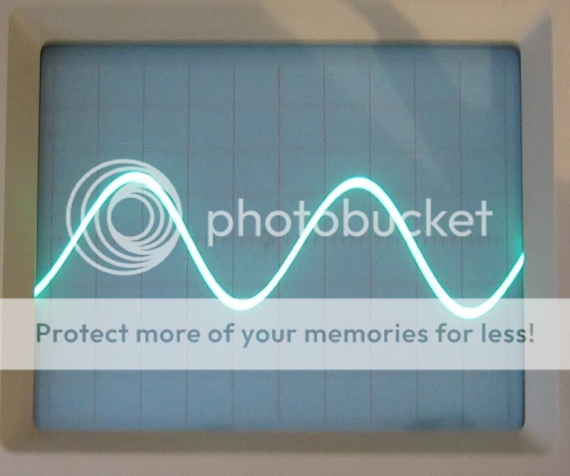
This is the A-X with a 1K sine wave

This is the Low TIM with same input.
Here's a shot with both amps hooked up being fed the same sine wave signal. The AX is on the bottom.
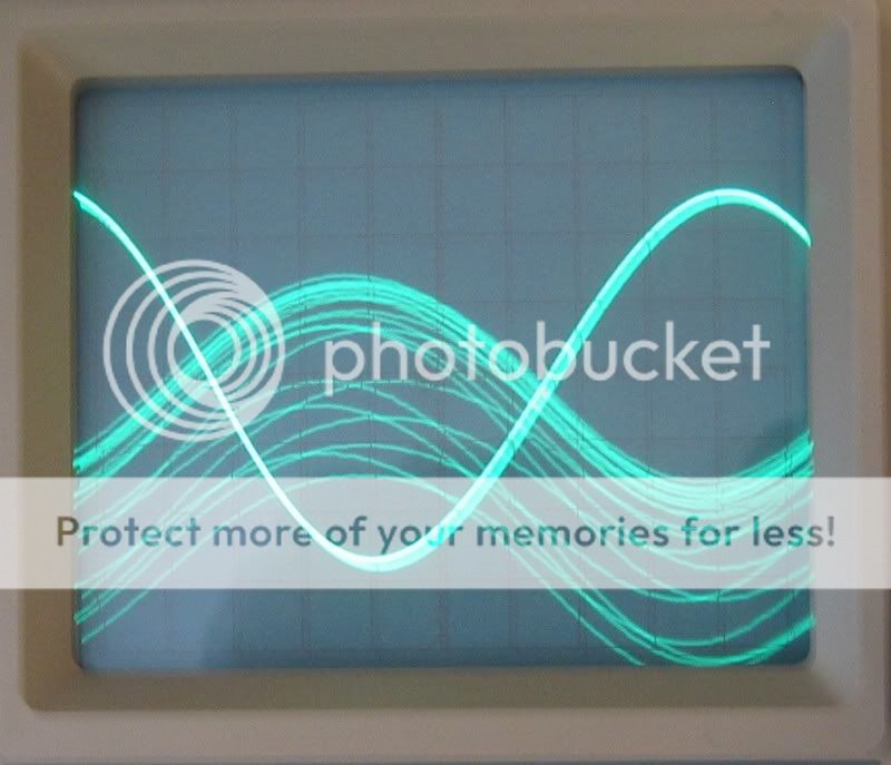
This is a shot of the Low TIM and the AX hooked up with the TIM/DIV turned down to 2mS.
I get that same trace when checking the PSU. Both sides are the same. I will try disconnecting the PSU form the board and see if it is still there. The trans is running too hot IMO. This is a very beefy trans.
Thanks again, Terry
EDIT:
I just disconnected one channel from the PSU. If I hook the scope to the + and - leads I get two straight lines. If I hook the scope to the + and - on the side that is still hooked up I get two of those jagged lines. Also, I measured the voltage of the two sides. The one that is still hooked to the board reads 15VDC. The other side measures 17VDC. It's dropping two volts. Can the board cause the PSU to produce ripple? I don't see any ripple on the PSU when it is not hooked up to the board.
Blessings, Terry
Let me show some more pics if I may.
Here is with these settings. The knob on the right is the TIME/DIV setting. It is set at .2mS
This is the A-X with a 1K sine wave
This is the Low TIM with same input.
Here's a shot with both amps hooked up being fed the same sine wave signal. The AX is on the bottom.
This is a shot of the Low TIM and the AX hooked up with the TIM/DIV turned down to 2mS.
I get that same trace when checking the PSU. Both sides are the same. I will try disconnecting the PSU form the board and see if it is still there. The trans is running too hot IMO. This is a very beefy trans.
Thanks again, Terry
EDIT:
I just disconnected one channel from the PSU. If I hook the scope to the + and - leads I get two straight lines. If I hook the scope to the + and - on the side that is still hooked up I get two of those jagged lines. Also, I measured the voltage of the two sides. The one that is still hooked to the board reads 15VDC. The other side measures 17VDC. It's dropping two volts. Can the board cause the PSU to produce ripple? I don't see any ripple on the PSU when it is not hooked up to the board.
Blessings, Terry
Ok,
First, second and third scope picture tells me the AX has less gain compared to the Low TIM, input signal being equal.
Fourth picture shows a high supply ripple for the AX.
The good news is that the amp is probably not oscillating. If you didn’t notice a pattern when in µS (not mS) mode my thinking would be correct.
The bad news is that something must be wrong with the transformer, presumably the wiring of the primary. Assuming you are in the 120V area and your transformer has a dual primary, it may be important how you wired the primary. You might have crossed the two windings.
/Hugo
Hi Hugo
The Transformer has two sets of primary windings. Two red wires and two black wires. I simply hooked the two black wires together and the two red wires together. I then connected the red wires to the AC hot lead and the black wires to the AC neutral. Why don't I see any ripple on the PSU when it is not under load?
On the side of the Transformer it says

Could it be that one set is for 50Hz and the other for 60Hz? I didn't think of that.
It will work with only one red and one black hooked up, but I was afraid it would not reach full mA without all four hooked up.
Blessings, Terry
The Transformer has two sets of primary windings. Two red wires and two black wires. I simply hooked the two black wires together and the two red wires together. I then connected the red wires to the AC hot lead and the black wires to the AC neutral. Why don't I see any ripple on the PSU when it is not under load?
On the side of the Transformer it says
Could it be that one set is for 50Hz and the other for 60Hz? I didn't think of that.
It will work with only one red and one black hooked up, but I was afraid it would not reach full mA without all four hooked up.
Blessings, Terry
Terry,
You need both primaries. It's unlikely that the 50 and 60 Hz is involved. It is a strange label (to me) as it doesn't mention the colours and the corresponding voltages.
We need someone more experienced in transformers to solve this before we do harm. As I said, I only guess something is wrong with the wiring. One thing is sure, it gets too hot.
As for the ripple when under load, this is not the case with my AlephX's. I'm still thinking what could be the cause.
/Hugo
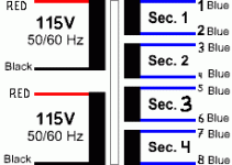
Transformer
Hi
My opinion:
Looks like you have 2 Pri's each rated at AC115V
Looks like you have 4 sets of Sec's each rated at AC12V
if so, then
The 2 Pri's should be connected in parallel (for US).
Red+Red Black+Black
If you only use one pri, then you only use/get ½ the VA rating of the Transformer.
The 4 Sec's can be connected as 2 and 2 in parallel.
1+3 2+4 5+7 6+8
Or you could use 4 bridges, 2 for each ch.
Ch.1: Bridge 1: 1 and 2 Bridge 2: 3 and 4
Ch.2: Bridge 3: 5 and 6 Bridge 4: 7 and 8
Best regards 😉
analogair
Toni
PS: Don't bother with the 50 Hz or 60 Hz.
In US you have 60 Hz, which, with a fullwave bridge, makes your ripple 120Hz. Here in Denmark we have 50Hz, and ends up with ripple at 100Hz. We need slightly bigger caps for filtering. 🙄
Attachments
- Home
- Amplifiers
- Pass Labs
- Aleph-X builder's thread